Load-sensitive rotation buffer valve and crane rotation hydraulic system

A rotary buffering, load-sensitive technology, applied in cranes, mechanical equipment, fluid pressure actuating devices, etc., can solve the problems of large swing of the turntable when stopped, large space-time travel when starting, and unstable output flow, etc., to eliminate pressure fluctuations, The effect of stable flow and small pressure shock

Active Publication Date: 2017-11-17
ANHUI LIUGONG CRANE
View PDF7 Cites 11 Cited by
  • Summary
  • Abstract
  • Description
  • Claims
  • Application Information

AI Technical Summary

Problems solved by technology

The steering reversing valve 1 of this patent adopts the principle of bypass shunt flow. During the operation process, the fluctuation of the pressure at the load end will directly affect the flow of A / B port, that is, the output flow is unstable, which will cause the rotation to be fast and slow, such as When the position of the operating handle remains unchanged, when the load increases, the hydraulic oil pumped out of the pump goes to the A / B port of the load end to decrease, and more hydraulic oil returns to the oil tank through the operation of the reversing valve 1, so that the rotation speed becomes slower. Similarly, when the load decreases, the slewing speed becomes faster. Large-tonnage cranes adopt this slewing technology. Due to the large inertial load, the space-time travel is large when starting, and the turntable swings greatly when stopping, which is a potential danger to both people and machines.

Method used


Image

  • Load-sensitive rotation buffer valve and crane rotation hydraulic system
  • Load-sensitive rotation buffer valve and crane rotation hydraulic system
  • Load-sensitive rotation buffer valve and crane rotation hydraulic system

Examples


Embodiment 1

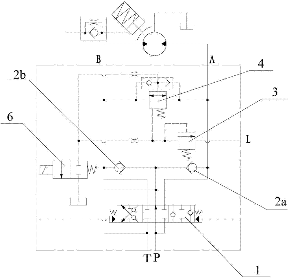
[0021] Load Sensing Swing Shock Valve 100, such as figure 2 As shown, including the valve body, the valve body has oil inlet port P, oil return port T, first working oil port A, second working oil port B, first pilot oil port a1, second pilot oil port The oil port b1, the oil discharge port L port, the A port and the B port are respectively used to communicate with the oil ports on both sides of the rotary motor 201, and the valve body is provided with a rotary reversing valve 101 and a pilot relief valve 103. The reversing valve 101 is a pilot-operated proportional reversing valve. The oil inlet port and the oil return port of the reversing reversing valve 101 are respectively connected with the P port and the T port of the valve body, and the two working oil ports of the reversing reversing valve 101 are respectively connected with A port and B port of the valve body are connected, and the first pilot oil port and the second pilot oil port of the rotary reversing valve 101 ...

Embodiment 2

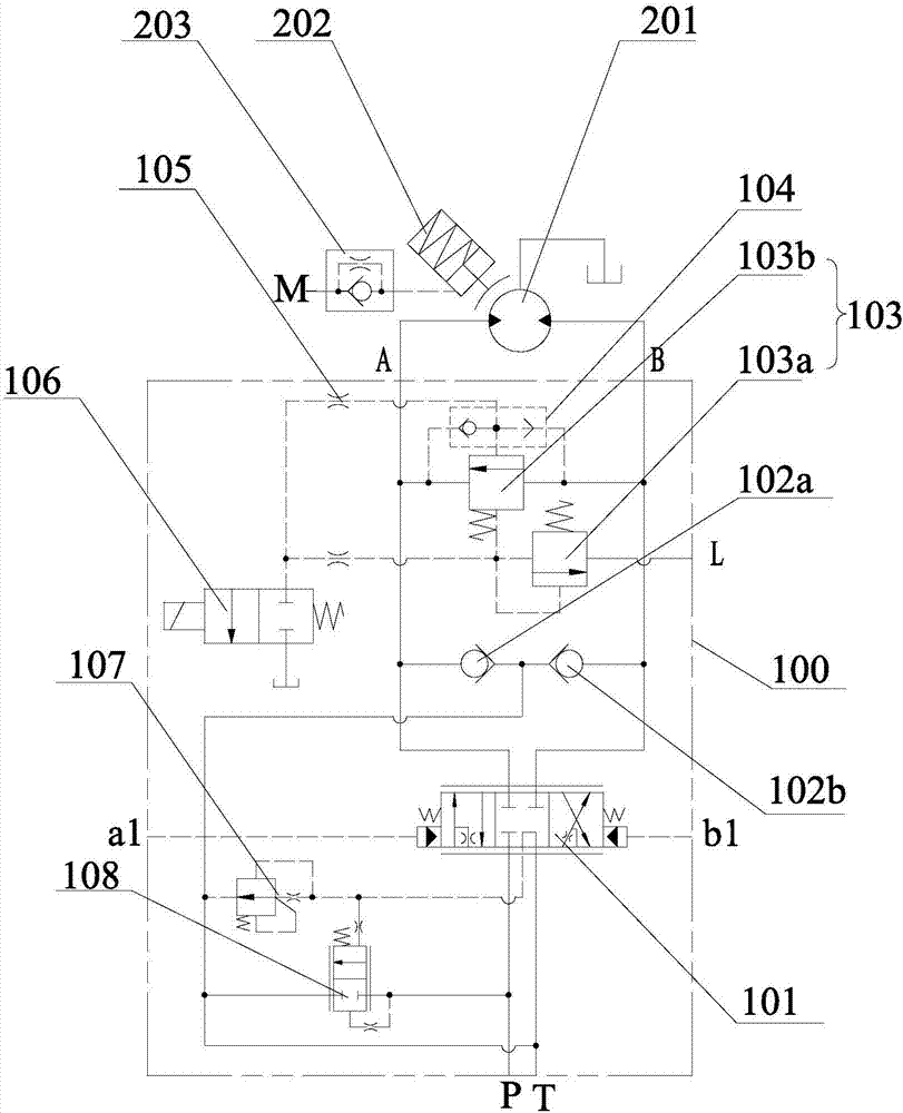
[0033] Load Sensing Swing Shock Valve 100, such as image 3 As shown, the difference between the present embodiment and the first embodiment lies in the use of the damping valve 109 and the bag body constant flow valve 107 .


PUM


Abstract

The invention discloses a load-sensitive rotation buffer valve and a crane rotation hydraulic system. A middle path of a rotation reversing valve is sequentially connected with a guide oil port of a three-way pressure compensation valve and an oil inlet of a constant flow valve through an LS feedback oil path, an oil inlet of the three-way pressure compensation valve is communicated with an oil inlet of a valve body, an oil outlet of the three-way pressure compensation valve is communicated with an oil returning opening of the valve body, an oil outlet of the constant flow valve is divided into two paths, one path is directly connected with the oil returning opening of the valve body, the other path is communicated with an oil inlet of a first one-way valve and an oil inlet of a second one-way valve at the same time, a speed adjusting valve is formed by the three-way pressure compensation valve and the rotation reversing valve, flow adjustment of a work oil port A and a work oil port B is achieved, flow is output proportionally, influences of the load are avoided, in the whole operation process, action is stable, fast and slow action is avoided, stable opening is achieved, during stopping, pressure impact is small, and a crane cannot rotate and swing.

Description

technical field [0001] The invention relates to the field of engineering machinery, in particular to a load-sensitive rotary buffer valve and a crane rotary hydraulic system. Background technique [0002] Medium and large-tonnage truck cranes have long booms and large load capacity. When the whole machine is slewing, the slewing inertia is large, resulting in poor slewing performance (large space-time travel when starting, and large slewing swing when stopping). If a closed system is used, Although the operating performance is superior, the cost is relatively high. [0003] Chinese patent 01142605.5 discloses a rotary buffer valve, the principle of which is figure 1 As shown, including the main valve body, there are oil inlet P, oil outlet T and the working oil port A / B connected to the hydraulic motor on the main valve body, and the oil inlet P and oil outlet T of the main valve body The ports are respectively connected to the oil inlet and the oil outlet of the steering ...

Claims


Application Information

Patent Timeline
Patent Type & Authority Applications(China)
IPC IPC(8): F15B13/02B66C23/86
CPCF15B13/02B66C23/86
Inventor 程伟徐尚国孙玉魁田善玉党伟冯文昌徐青山
Owner ANHUI LIUGONG CRANE
Why Eureka
Try Eureka