Supercharge Your Innovation With Domain-Expert AI Agents!

Cam grooving machine

A cam, cam surface technology, used in groove needles, mechanical equipment, engine components, etc., can solve problems such as low production rate and complexity

Active Publication Date: 2018-07-17
VICTAULIC
View PDF21 Cites 0 Cited by
  • Summary
  • Abstract
  • Description
  • Claims
  • Application Information

AI Technical Summary

Problems solved by technology

These considerations have resulted in complex prior art arrangements which, for example, require an actuator to force the roller into engagement with the pipe element and the operator to be able to adjust the roller stroke to achieve the desired groove radius
Additionally, prior art roll grooving machines have low production rates, often requiring multiple revolutions of the tube element to achieve a completed circumferential groove

Method used


Image

  • Cam grooving machine
  • Cam grooving machine
  • Cam grooving machine

Examples


Embodiment Construction

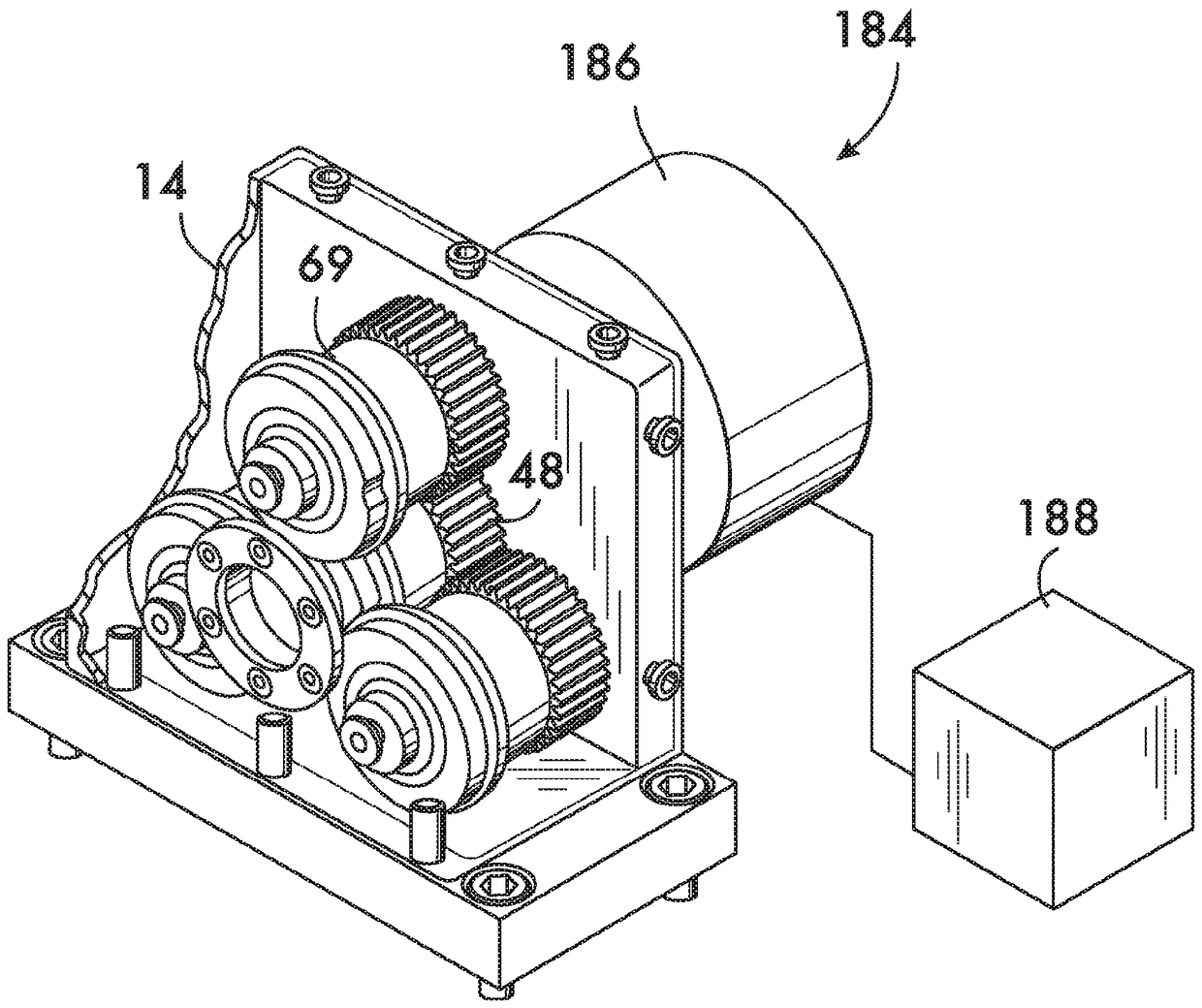
[0042] figure 1 An exemplary apparatus 10 is shown for cold working a tubular element, such as forming a circumferential groove in the outer surface of the tubular element. Device 10 is shown pivotally mounted on a rotary power chuck 12 . Such chucks are well known, an example being the Ridgid 300 powered driver sold by Ridgid of Elyria, Ohio.

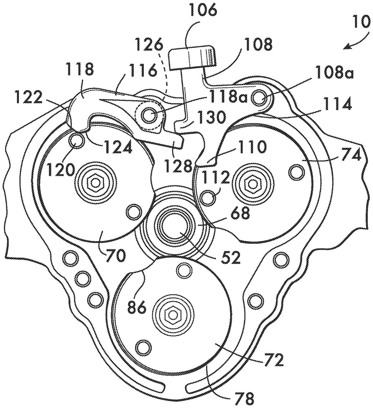
[0043] figure 2 An exploded view of device 10 including housing 14 is shown. The housing 14 is formed of a housing body 16 and a cover 18 . A plurality of gears (in this example three gears 20, 22 and 24) are rotatably mounted on respective shafts 26, 28 and 30 which are supported by housing body 16 and cover 18 and define respective Axes of rotation 32 , 34 and 36 . The axes 32, 34 and 36 are arranged parallel to each other. In one practical design, each gear 20 , 22 and 24 has a corresponding flanged bush 38 and may also have a thrust washer 40 and a compression spring 42 . A compression spring 42 acts between the gears 20, 2...


PUM


Abstract

A device for cold working pipe elements has two or more cams, each having a gear which meshes with a pinion to turn all of the cams. Each cam has a cam surface with a region of increasing radius and may have a region of constant radius extending around a cam body. Each cam also has a traction surface extending around a cam body. A discontinuity in each cam surface is aligned with a gap in the traction surface of each cam. The discontinuities and gaps provide clearance for insertion and removal of the pipe element between the cams to form a circumferential groove when the cams are rotated.

Description

[0001] Cross References to Related Applications [0002] This application is based on U.S. Provisional Application No. 62 / 260,922, filed November 30, 2015, U.S. Provisional Application No. 62 / 359,395, filed July 7, 2016, and U.S. Provisional Application No. 62 / 363,892, filed July 19, 2016 and U.S. Provisional Application No. 62 / 395,747 filed September 16, 2016 and claiming the benefit of priority from them, the entire contents of which are incorporated herein by reference. technical field [0003] The present invention relates to machines for cold working tubular elements using cams. Background technique [0004] Cold working of pipe elements (eg, imprinting circumferential grooves in pipe elements to accept mechanical pipe couplings) is advantageously accomplished by use of a roll grooving machine having an inner roller that engages the inside surface of the pipe element and simultaneously engages the pipe The outside surface of the element and the outer roller opposite th...

Claims


Application Information

Patent Timeline
Patent Type & Authority Applications(China)
IPC IPC(8): B21D15/04B21D15/06B21D17/02B21D17/04B21H1/20B21H1/22
CPCB21H7/182B21D17/04B21D15/04B21D15/06B21D17/02B21H1/20B21H1/22F16H53/00B21D15/00
Inventor D.R.多尔
Owner VICTAULIC
Features
  • R&D
  • Intellectual Property
  • Life Sciences
  • Materials
  • Tech Scout
  • Unparalleled Data Quality
  • Higher Quality Content
  • 60% Fewer Hallucinations
Learn More