A method for optimizing a work cycle in a robot system

A technology of robot system and work cycle, applied in general control system, control/regulation system, instrument, etc., can solve problems such as not optimal work cycle

Active Publication Date: 2018-07-17
ABB (SCHWEIZ) AG
View PDF11 Cites 0 Cited by
  • Summary
  • Abstract
  • Description
  • Claims
  • Application Information

AI Technical Summary

Problems solved by technology

Therefore, the work area division is not part of the optimization problem, and if the operator fails to choose the optimal work area division for a given layout, the resulting duty cycle may not be optimal either

Method used


Image

  • A method for optimizing a work cycle in a robot system
  • A method for optimizing a work cycle in a robot system
  • A method for optimizing a work cycle in a robot system

Examples


Embodiment Construction

[0023] In the context of this disclosure, "cycle time" may refer to the time required for a robotic system to perform a task sequence once. However, due to the periodic nature of work cycles, subsequent work cycles may start before the previous work cycle is ready. Thus, the term "cycle time" may also refer to the average time required for a robotic system to perform a task sequence when performing a (mass) sequence of tasks.

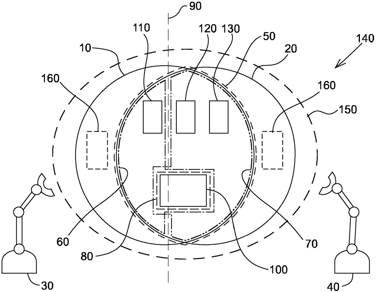
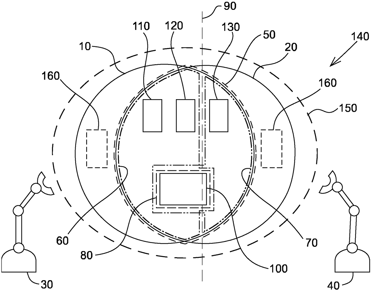
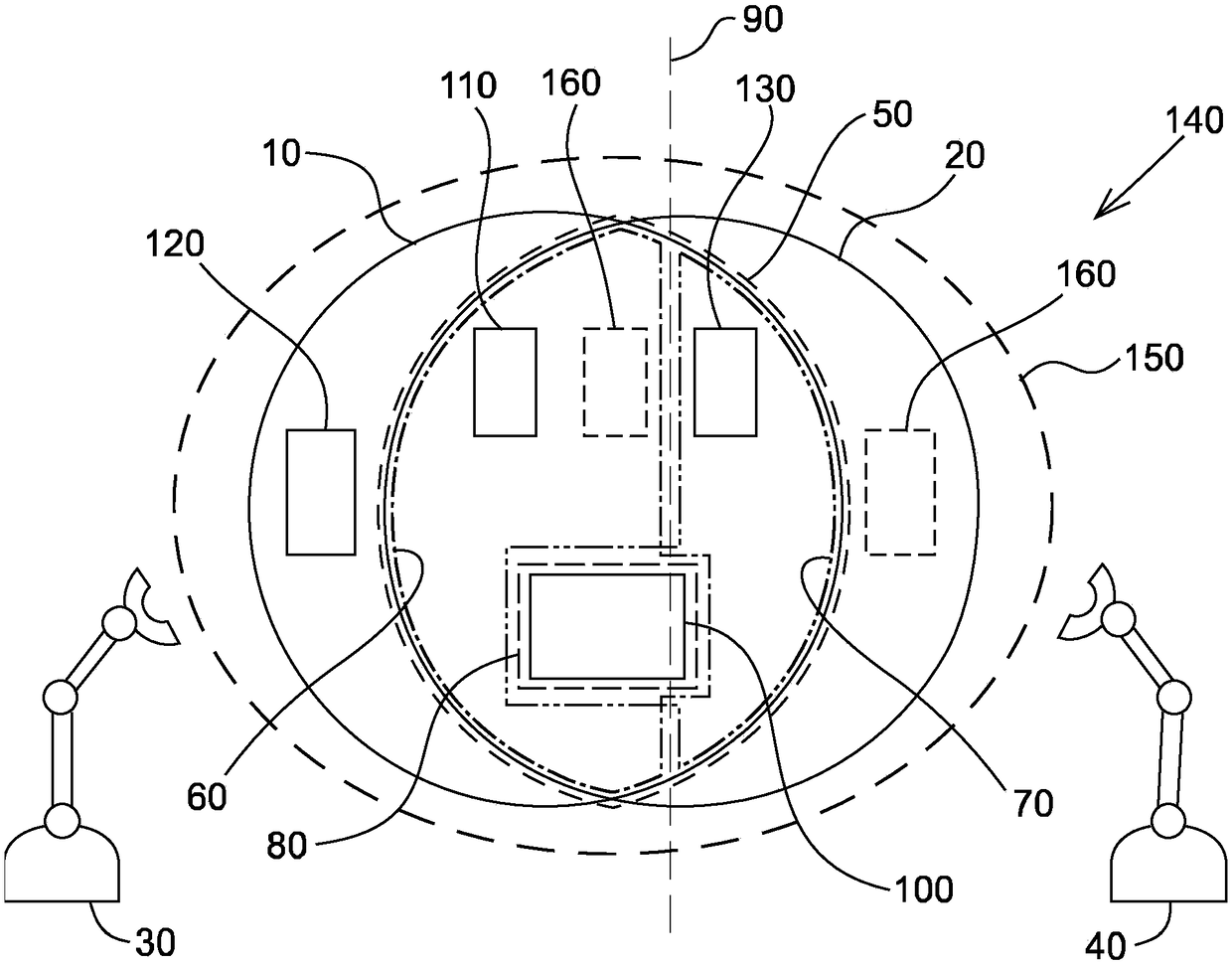
[0024] refer to figure 2 , given a layout with figure 1 The same in , and the overall task is the same (fit the three parts together at the fixture). However, the working area division differs in that the first feeder and the second feeder are assigned to the first manipulator, and only the third feeder is assigned to the second manipulator. suppose to pass figure 2 A division of the working area can be achieved than by figure 1 The work area division of the shorter cycle time, then the optimization problem is restricted to according to figure 1...


PUM


Abstract

Provided is a method for a robot system. The method for a robot system has at least two manipulators with a common work area, wherein the layout of the robot system is defined and the common work areabetween the at least two manipulators is divided to thereby obtain a work area division. The method is characterized in that at least one of the previous steps is repeated to thereby obtain a plurality of different combinations of layouts and work area divisions. For each of the combinations, a cycle time for at least one work cycle is calculated and the best cycle time is chosen to optimize thework cycle of the robot system.

Description

technical field [0001] The invention relates to duty cycle optimization in robotic systems having two or more manipulators with a common work area. Background technique [0002] refer to figure 1 , in the context of the present disclosure, "maximum working area" 10, 20 refers to the volume achievable by a manipulator 30, 40, which volume is constrained by the mechanical structure of the respective manipulator. A "common work area" 50 refers to a portion of the maximum work area accessible to each of the plurality of manipulators, the corresponding volume being dependent on the relative positions of the manipulators and constrained by the manipulator's mechanical structure. By "dedicated working area" is meant the part of the maximum working area that only the corresponding manipulator can reach, ie the private working area is the result of subtracting the common working area from the maximum working area. "Assigned working area" 60 , 70 means a part of the common working a...

Claims


Application Information

Patent Timeline
IPC IPC(8): B25J9/16G05B19/042G05B19/418
CPCB25J9/1605B25J9/1682G05B19/0426G05B19/41885G05B2219/31054G05B2219/32085G05B2219/40417Y02P90/02
Inventor J·韦森F·克努塔
Owner ABB (SCHWEIZ) AG
Why Eureka
Try Eureka