Heat dissipation control system and method thereof

A control system and control method technology, applied in the direction of instruments, electrical digital data processing, digital data processing components, etc., can solve problems such as large noise, inconvenience, and inability to calibrate the heat dissipation system, so as to reduce noise and maintain heat dissipation The effect of power, heat dissipation and noise balance

Pending Publication Date: 2021-09-24
ASUSTEK COMPUTER INC
View PDF0 Cites 0 Cited by
  • Summary
  • Abstract
  • Description
  • Claims
  • Application Information

AI Technical Summary

Problems solved by technology

[0002] In today's assembled computers, the control signals of the radiator and fan are connected to the motherboard for unified control, but because the components in the assembled computer are purchased and installed by the user himself, so each assembled computer Not only is the cooling capacity very different, but the cooling system cannot be calibrated before leaving the factory like branded packaged computers
[0003] When controlling the fan on the motherboard, the duty cycle issued by the BIOS or software will control the fan rotation through the fan control module, so whether it is the BIOS or the software, the fan speed is controlled by the duty cycle temperature curve , the larger the value of the duty cycle, the faster the fan speed, so it can be seen from the temperature curve of the duty cycle that when the temperature is higher, the fan speed is higher, but the higher the fan speed is, the greater the fan speed will be. noise
[0004] The current practice is that the mainboard will preset the duty ratio temperature curve in the fan control module before leaving the factory, but because the RPM of each fan for the same duty ratio is different, so the mainboard The control interface will be opened for users to adjust the fan speed by themselves. In this way, if users want to adjust to a state of balanced heat dissipation and noise, they must constantly adjust the duty cycle temperature curve by themselves, and test and verify it back and forth to complete the adjustment. very inconvenient

Method used


Image

  • Heat dissipation control system and method thereof
  • Heat dissipation control system and method thereof
  • Heat dissipation control system and method thereof

Examples


Embodiment Construction

[0017] The positional relationships described in the following embodiments include: up, down, left and right. Unless otherwise specified, they are all based on the directions in which the components are drawn in the drawings.

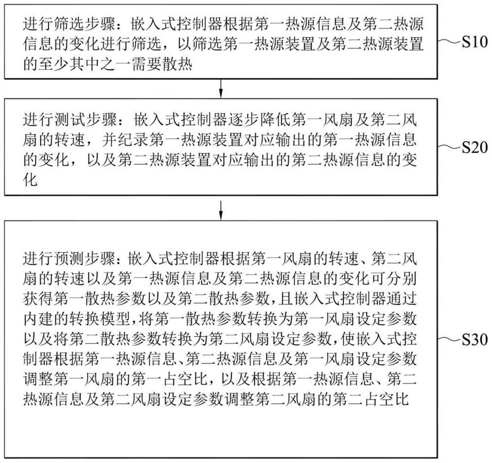
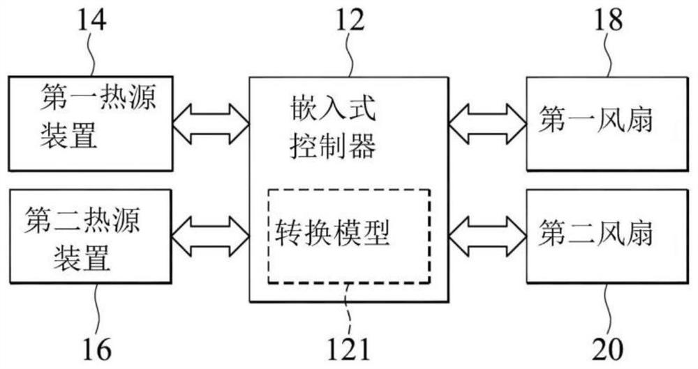
[0018] Please also see figure 1 and figure 2 As shown, the heat dissipation control method is executed by the embedded controller 12, the embedded controller 12 at least receives the first heat source information from the first heat source device 14 and the second heat source information from the second heat source device 16, and according to the first heat source The information and the second heat source information dynamically adjust at least two fans, including the first fan 18 and the second fan 20 . The heat dissipation control method sequentially includes a screening step in step S10, a testing step in step S20, and a predicting step in step S30.

[0019] As shown in step S10, the screening step is carried out: when the computer is running, th...


PUM


Abstract

The invention provides a heat dissipation control system. The heat dissipation control system comprises a fan control module, a chipset, a central processing unit, a display card card fan module, a display card chip and an embedded controller. The fan control module is used for controlling a first fan, and the first fan is set to correspond to a first duty ratio; the chipset is electrically connected with the fan control module; the central processing unit is used for outputting the first heat source information; the display card fan module is used for controlling a second fan, and the second fan is set to correspond to a second duty ratio; the display card chip is electrically connected with the display card fan module and is used for outputting the second heat source information; the embedded controller is electrically connected with the chipset, the central processing unit and the display card chip. The embedded controller dynamically adjusts the first duty ratio and the second duty ratio according to the first heat source information and the second heat source information.

Description

technical field [0001] The present application relates to a heat dissipation control system, especially a heat dissipation control system using a fan. Background technique [0002] In today's assembled computers, the control signals of the radiator and fan are connected to the motherboard for unified control, but because the components in the assembled computer are purchased and installed by the user himself, so each assembled computer Not only is the cooling capacity very different, but the cooling system cannot be calibrated at the factory like brand-name box PCs. [0003] When controlling the fan on the motherboard, the duty cycle issued by the BIOS or software will control the fan rotation through the fan control module, so whether it is the BIOS or the software, the fan speed is controlled by the duty cycle temperature curve , the larger the value of the duty cycle, the faster the fan speed, so it can be seen from the temperature curve of the duty cycle that when the t...

Claims


Application Information

Patent Timeline
IPC IPC(8): G06F1/20
CPCG06F1/206
Inventor 陈侑骏林官毅王文志罗其钧郑榆杨正宜黄以民郑富元侯永晟
Owner ASUSTEK COMPUTER INC
Why Eureka
Try Eureka