Optical laminate and image display device

A technology of optical laminates and protective layers, applied in optics, optical components, identification devices, etc., can solve the problems of external light reflection and reflection, and achieve the effect of excellent anti-reflection function

Active Publication Date: 2018-07-17
NITTO DENKO CORP
View PDF16 Cites 2 Cited by
  • Summary
  • Abstract
  • Description
  • Claims
  • Application Information

AI Technical Summary

Problems solved by technology

However, in reality, due to the influence of the conductive layer forming process and the treatment to improve the toughness of the base material, even in an isotropic base material, some anisotropy will appear.
As a result, even if a circular polarizing film is installed, problems such as reflection of external light and reflection of the background may occur, which have not yet been resolved.

Method used


Image

  • Optical laminate and image display device
  • Optical laminate and image display device
  • Optical laminate and image display device

Examples


Embodiment 1

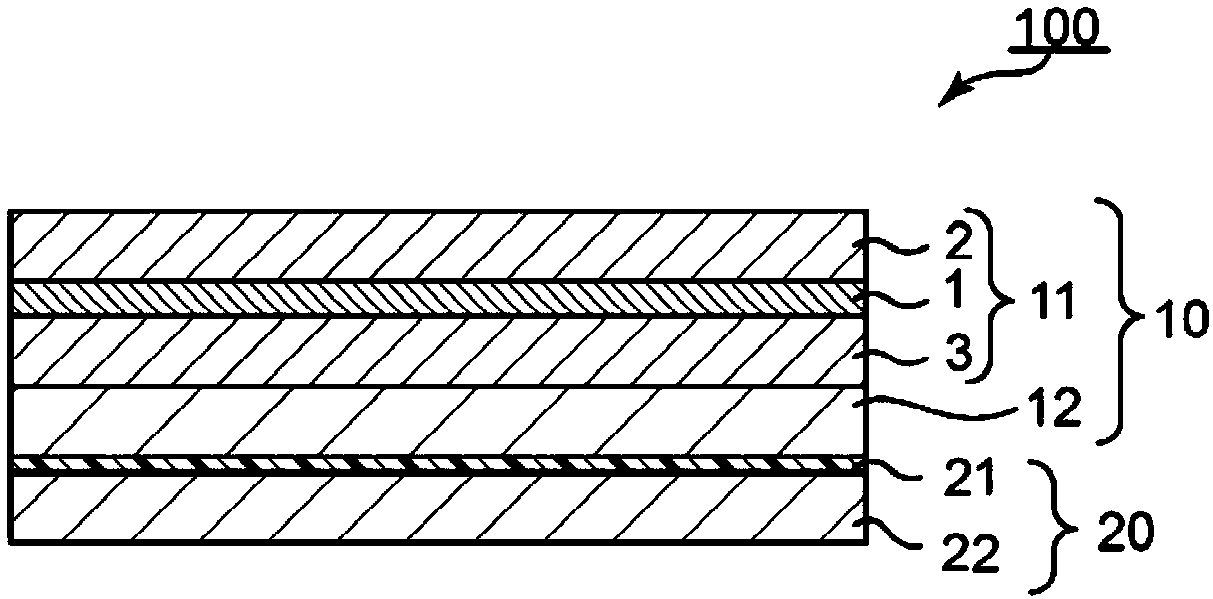
[0104] The optical laminates having the configurations shown in Table 1 below were evaluated for their reflection characteristics based on the front hues a and b using an optical simulator (manufactured by Shintec, trade name "LCD Master V8"). .

[0105] In addition, a light source (D65 light source registered in "LCD Master V8") is arranged on the opposite side of the polarizer to the retardation layer, and a reflector ( Ideal Reflector Idea-Reflector registered in "LCD Master V8").

[0106] In addition, the front hues a and b were calculated with the same configuration as in Table 1 except that the base material was not included, and the results were used as a reference.

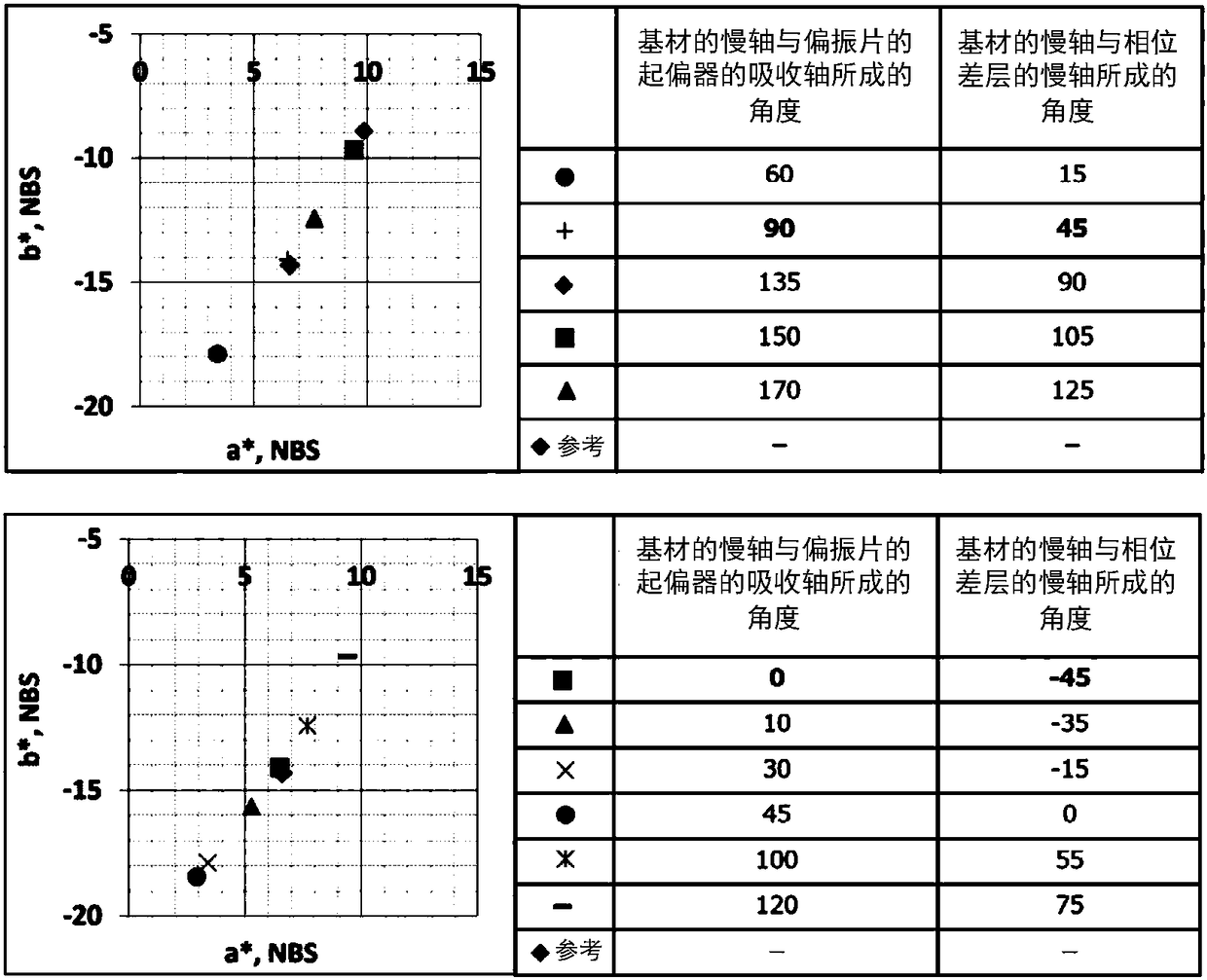
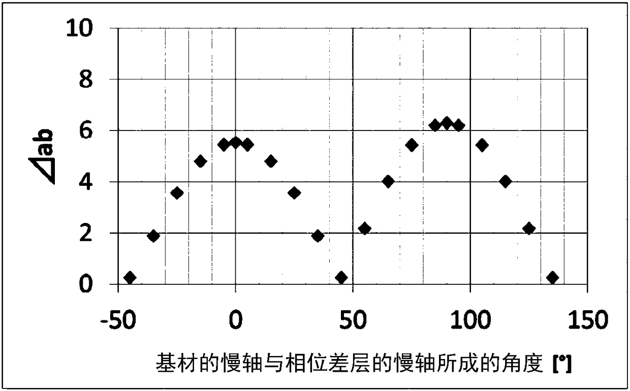
[0107] In this evaluation, the slow axis angle of the base material was changed as described below, and the simulation was performed, and the reflection characteristics of the optical laminate were evaluated by comparison with the reference.

[0108] [Table 1]

[0109]

Embodiment 1-1

[0111] The angle formed by the slow axis of the base material and the absorption axis of the polarizer of the polarizing plate was set to 90°. That is, the angle formed by the slow axis of the base material and the slow axis of the retardation layer was set to 45°.

Embodiment 1-2

[0113] The angle formed by the slow axis of the base material and the absorption axis of the polarizer of the polarizing plate was set to 0°. That is, the angle formed by the slow axis of the base material and the slow axis of the retardation layer was set to -45°.


PUM

PropertyMeasurementUnit
thicknessaaaaaaaaaa
thicknessaaaaaaaaaa
thicknessaaaaaaaaaa

Abstract

The invention provides an optical laminate that has an excellent anti-reflective function despite being provided with a substrate having optical anisotropy (also referred to below as an anisotropic substrate). The optical laminate comprises the following in this order: a polarizing plate including a polarizer and a protective layer arranged on at least one side of the polarizer; a retardation layer; a conductive layer; and a substrate. The in-plane retardation Re (550) of the substrate is larger than 0 nm and the angle formed by the slow axis of the substrate and the slow axis of the retardation layer is either -40 degrees to -50 degrees or 40 degrees to 50 degrees.

Description

technical field [0001] The present invention relates to an optical laminate and an image display device using the same. Background technique [0002] In recent years, with the spread of thin displays, displays (organic EL display devices) mounted with organic EL (Electroluminescence) panels have been proposed. Since the organic EL panel has a highly reflective metal layer, problems such as reflection of external light and reflection of the background are likely to occur. Therefore, it is known to prevent these problems by arranging the circular polarizer on the visible side. On the other hand, a so-called in-cell touch panel type input display device in which a touch sensor is inserted between a display unit (eg, an organic EL unit) and a polarizing plate is in high demand. In the input display device having such a configuration, since the distance between the image display unit and the touch sensor is relatively short, a natural input operation feeling can be given to the...

Claims


Application Information

Patent Timeline
Patent Type & Authority Applications(China)
IPC IPC(8): G02B5/30B32B7/02B32B27/36G02F1/1335G02F1/13363G09F9/30H01L27/32H01L51/50H05B33/02
CPCB32B27/36G02F1/1335G02F1/13363G02B5/30G09F9/30H05B33/02G02B5/305H10K59/00H10K50/00B32B7/023
Inventor 角村浩武田健太郎饭田敏行
Owner NITTO DENKO CORP
Why Eureka
Try Eureka