
Rat catcher and murine monitoring system

A technology for rodents and monitoring centers, applied in transmission systems, animal traps, electrical components, etc., can solve problems such as lack of monitoring functions

Pending Publication Date: 2018-07-20
ACADEMY OF MILITARY MEDICAL SCI +1
View PDF12 Cites 10 Cited by
  • Summary
  • Abstract
  • Description
  • Claims
  • Application Information

AI Technical Summary

Problems solved by technology

Does not have the monitoring function and cannot provide effective data for rodent monitoring

Method used


Image

  • Rat catcher and murine monitoring system
  • Rat catcher and murine monitoring system
  • Rat catcher and murine monitoring system

Examples


Embodiment Construction

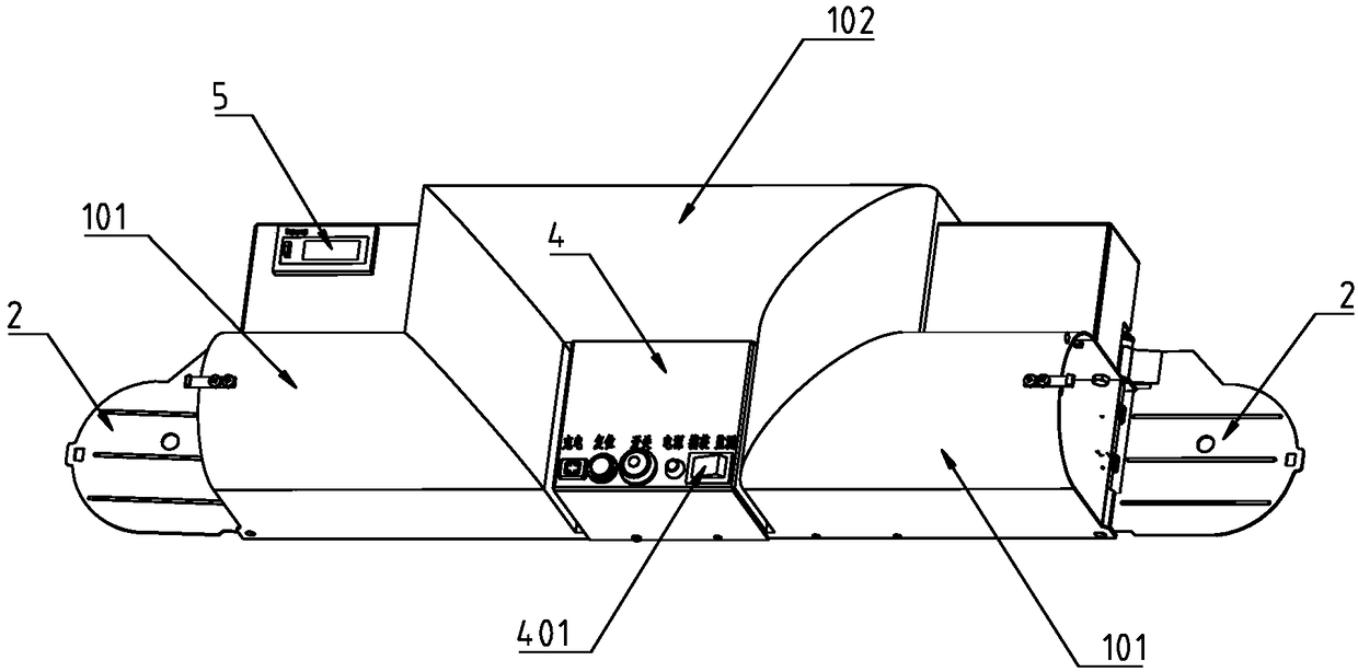
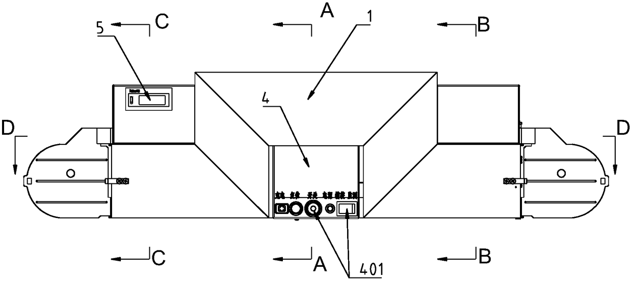
[0028] The structure of the mouse trap in the embodiment of the present invention is as follows: Figure 1 to Figure 8 Shown, including the mouse trap mechanism, control circuit and power circuit.

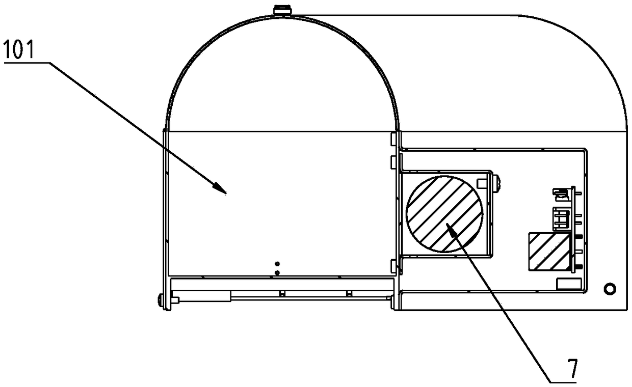
[0029] The mouse catching mechanism includes a casing, and the casing includes a curved mouse passage 1, which is conducive to luring rodents to enter. The upper part of the mouse passage 1 is semicircular, and the lower part is rectangular, which is suitable for rodents to pass through. There is a section of straight passage 101 at both ends of the rat passage 1, and a door-shaped bend 102 is arranged in the middle of the rat passage 1.

[0030] An electric control door is installed at both ends of channel 1. The control circuit includes an electric control switch to close the electric control door, such as Figure 6 and Figure 7 As shown, the electric control door includes a passage door 2, a torsion spring 8 and a door shaft 9. The passage door 2 is installed at the end of t...


PUM


Abstract

The invention discloses a rat catcher and a murine monitoring system. The rat catcher comprises a rat catcher mechanism, a control circuit and a power supply circuit, wherein the control circuit comprises a main controller, an infrared detection module, an infrared imaging device, a wireless communication module and a man-machine interaction device, the control end of the infrared photographic device is connected with the control signal output end of the main controller; and the data output of the infrared photographic device is connected with the main controller. The murine monitoring systemcomprises the above-mentioned rat catcher, the monitoring center and the smart phone, wherein the rat catcher is in wireless connection with the monitoring center and the smart phone; smartphones control the rat catcher through SMS, and the monitoring center controls the rat catcher, through instructions. The rat catcher and murine monitoring system not only capture murine, but also has monitoringfunction to provide effective data for monitoring the mouse situation.

Description

[technical field] [0001] The invention relates to rodent monitoring and capture, in particular to a mouse trapping device and a rodent monitoring system. [Background technique] [0002] Rodent infestation is one of the four major biological disasters in agriculture, and it is also an important medium for spreading various human diseases. [0003] The utility model whose patent number is CN201420385236.7 discloses an automatic mouse trap. Its rib plate (3) is arranged on the upper and lower ends of the device body (1), and the device body (1) has a built-in mouse trap channel (6), and two draw-in groove tracks (4) are vertically arranged at the left two ends of the device body (1). The door (5) is slidably placed in the rails (4) of the two card slots, the stopper (7) is arranged at the lower left end of the body (1), and is movably connected with the lower end of the dodge door (5), and the dodge door control mechanism is set in the body (1) In the upper end and the box bo...

Claims


Application Information

Patent Timeline
Patent Type & Authority Applications(China)
IPC IPC(8): A01M23/38H04W4/14H04L29/08
CPCA01M23/38H04L67/025H04L67/12H04W4/14
Inventor 董言德赵彤言李春晓邢丹郭晓霞张恒端沈春华
Owner ACADEMY OF MILITARY MEDICAL SCI
Learn More