Working method of milling machine clamp

A working method and milling machine fixture technology, applied in the direction of clamping, manufacturing tools, metal processing equipment, etc., can solve the problems of reducing work efficiency and high labor intensity of workers, so as to improve production efficiency, reduce labor intensity of workers, and have a wide range of applications Effect

Inactive Publication Date: 2018-07-20
太仓市万丰塑料制品有限公司
View PDF7 Cites 1 Cited by
  • Summary
  • Abstract
  • Description
  • Claims
  • Application Information

AI Technical Summary

Problems solved by technology

[0003] But at present, most of the milling machine fixtures still stay at one time to tighten and fix and can only load one workpiece, which requires workers to load the workpiece frequently, which greatly reduces the work efficiency, and the labor intensity of the workers is high.

Method used


Image

  • Working method of milling machine clamp
  • Working method of milling machine clamp

Examples


Embodiment

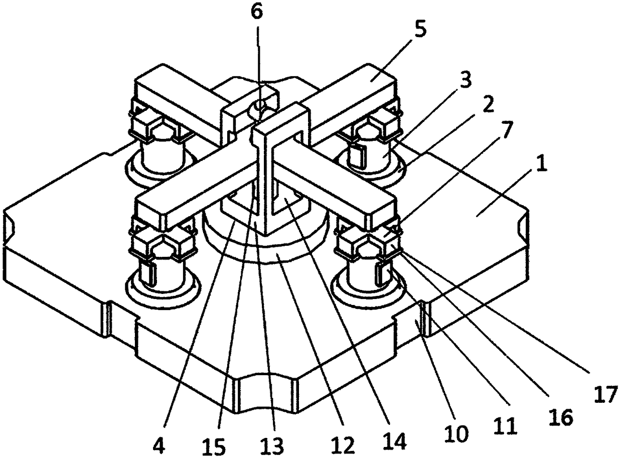
[0021] The working method of a milling machine fixture of the present invention, such as figure 1 with figure 2 As shown, including the following steps:

[0022] 1) The control module sends an instruction to run the steering drive system, drives the middle turntable 4 to turn, drives the crimping piece 7 to move to the loading and unloading station, the steering drive system stops, and the crimping piece 7 is kept at the loading and unloading station;

[0023] 2) Replace the workpiece: Take down the processed workpiece, and install a new set of workpieces on the support 3;

[0024] 3) The control module issues a command to make the steering drive system run in the reverse direction, drive the intermediate turntable 4 to turn, drive the crimping piece 7 back to the crimping station, the steering drive system stops, and the crimping piece 7 is kept at the crimping station;

[0025] 4) The control module issues an instruction to run the lifting drive system, drives the adjusting pressur...


PUM


Abstract

The invention discloses a working method of a milling machine clamp. The working method of the milling machine clamp includes the following steps that a middle rotating disk is driven to turn, and a pressing connection piece is driven to move to a loading and unloading station, and is kept at the loading and unloading station; a workpiece is replaced; the middle rotating disk is driven to turn, the pressing connection piece is driven to return to a pressing connection station, and the pressing connection piece is kept at the pressing connection station; an adjusting pressing rod is driven to perform downward pressing, and the pressing connection piece is pushed to gradually press the workpiece; a pressure sensor detects a pressure value between the pressing connection piece and the workpiece; when the pressure value is larger than a set value, a lifting driving system stops, and the pressing connection piece is kept at the pressing position; after machining is completed, the adjustingpressing rod is driven to rise, and the workpiece is loosened; and the adjusting pressing rod rises to the set position. The working method of the milling machine clamp can achieve that a plurality ofworkpieces are loaded and disassembled at a time, the basic time and the auxiliary time for workpiece machining are shortened to a great extent, and the production efficiency is effectively improved;and the clamping pressure on the workpiece can be automatically adjusted, and the application range is wide.

Description

Technical field [0001] The invention relates to the field of milling machine fixtures, and in particular to a working method of milling machine fixtures. Background technique [0002] With the continuous development of milling machine fixtures, the requirements for reducing the basic time and auxiliary time of workpiece processing are constantly increasing to improve production efficiency, reduce labor intensity of workers, and reduce production costs. [0003] However, most of the milling machine fixtures are still fixed at a time and can only load one workpiece at a time, requiring workers to load the workpiece frequently, which greatly reduces the work efficiency and the labor intensity of the workers. Summary of the invention [0004] The purpose of the invention: The present invention discloses a working method of a milling machine fixture, which can load multiple workpieces at one time. After the workpieces are processed, they can be disassembled at one time, which greatly sho...

Claims


Application Information

Patent Timeline
Patent Type & Authority Applications(China)
IPC IPC(8): B23Q3/06
CPCB23Q3/06
Inventor 陆娇娇张海金
Owner 太仓市万丰塑料制品有限公司
Why Eureka
Try Eureka