Shearing force groove structure for underwater concrete bottom sealing and construction method of shearing force groove structure

An underwater concrete and shear trough technology, applied in infrastructure engineering, construction, etc., can solve problems such as engineering accidents, difficulty in meeting engineering needs, and difficulty in completely penetrating the water-proof curtain of a confined aquifer, and achieve reliable connection, Guaranteed water tightness effect

Pending Publication Date: 2018-07-20
WUHAN MUNICIPAL ENG DESIGN & RES INST
View PDF0 Cites 0 Cited by
  • Summary
  • Abstract
  • Description
  • Claims
  • Application Information

AI Technical Summary

Problems solved by technology

However, for those with large excavation depth, extremely large thickness and buried depth of the confined aquifer, it is difficult for the water-proof curtain to completely penetrate the confined aquifer, and there are extremely sensitive buildings (structures) within

Method used


Image

  • Shearing force groove structure for underwater concrete bottom sealing and construction method of shearing force groove structure
  • Shearing force groove structure for underwater concrete bottom sealing and construction method of shearing force groove structure
  • Shearing force groove structure for underwater concrete bottom sealing and construction method of shearing force groove structure

Examples


Example Embodiment

[0034] The principles and features of the present invention will be described below with reference to the accompanying drawings. The examples cited are only used to explain the present invention and not used to limit the scope of the present invention.

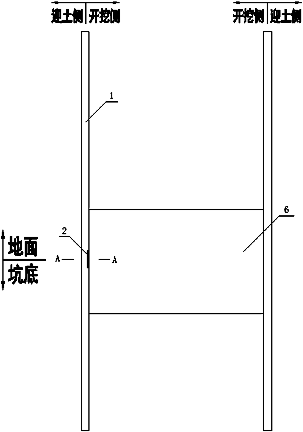
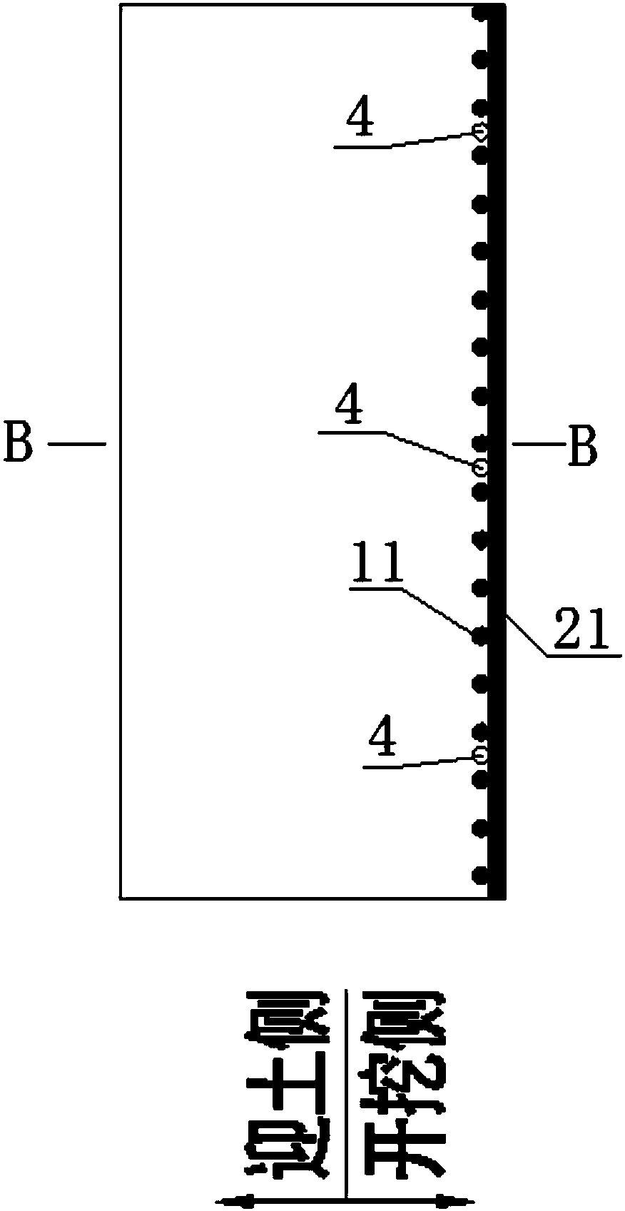
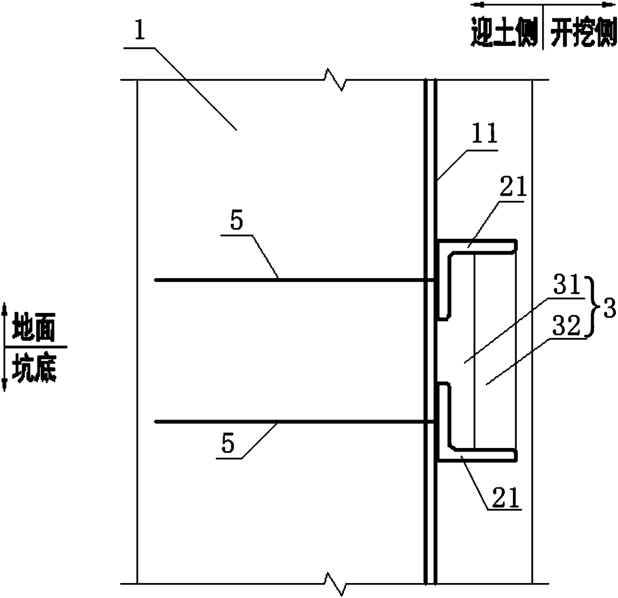
[0035] Such as figure 1 , figure 2 , image 3 with Figure 4 As shown, a shear trough structure used for underwater concrete sealing includes a foundation pit excavated on the ground, surrounded by a surrounding structure 1 higher than the ground, and also includes an angle steel pair 2, a transition The plate 3 and a plurality of embedded flushing pipes 4, the angle steel pair 2 are arranged on the inner side of the enclosure structure 1 at intervals, and the two angle steels 21 of the angle steel pair 2 are arranged at relatively intervals and are respectively located on the upper and lower sides of the ground On both sides, two rows of anchoring steel bars 5 corresponding to the angle steel 21 are embedded in the inner envelo...


PUM


Abstract

The invention relates to a shearing force groove structure for underwater concrete bottom sealing and a construction method of the shearing force groove structure. The shearing force groove structurecomprises a foundation pit excavated on the ground, an enclosure structure is arranged around the foundation pit in a surrounding manner, and the shearing force groove structure further comprises steel angle pairs, transition plates and pre-buried flushing pipes, wherein the steel angle pairs are arranged on the inner side of the enclosure structure at intervals and in a surrounding mode, and thetwo steel angles in each steel angle pair are arranged oppositely at intervals; two rows of anchoring steel bars corresponding to the steel angles are embedded in the enclosure structure in an up-and-down interval mode, and the ends, close to the steel angle pairs, of the anchoring steel bars extend out of the enclosure structure and then are fixedly connected with the corresponding steel angles;each transition plate is arranged between the two steel angles in each steel angle pair, the pre-buried flushing pipes are arranged in the enclosure structure, and a plurality of water outlet holes are formed in the positions, corresponding to the steel angle pairs, of the pre-buried flushing pipes and the holes face the transition plates. According to the shearing force groove structure, reliableconnection between the bottom sealing concrete and the enclosure structure is achieved, the water tightness of the bottom sealing concrete is guaranteed, and huge water pressure at the bottom of thepit can be borne.

Description

technical field [0001] The invention relates to the technical field of underground engineering design and construction, in particular to a shear groove structure for underwater concrete bottom sealing and a construction method thereof. Background technique [0002] In many cities in my country, there are generally multiple layers of confining aquifers with stable thickness and soft soil layers with high water content. With the development of urban transportation and underground space, the excavation of deep and large foundation pits has involved these layers. As the environmental conditions of the foundation pit are becoming more and more complex, the requirements for the control of the deformation of the foundation pit are becoming more and more stringent. Therefore, during the excavation of deep foundation pits, it is not only necessary to treat the confined water at the bottom of the pit to prevent inrush The damage endangers the safety of the project, and it is also nec...

Claims


Application Information

Patent Timeline
IPC IPC(8): E02D15/02
CPCE02D15/02
Inventor 胡云华陈建斌彭定新
Owner WUHAN MUNICIPAL ENG DESIGN & RES INST
Why Eureka
Try Eureka