Micro-gyroscope sliding mode control method with error limitation

A control method and micro-gyroscope technology, applied in the direction of adaptive control, general control system, control/adjustment system, etc., can solve the problems that the MEMS micro-gyroscope error indicators cannot meet the design requirements, etc.

Inactive Publication Date: 2018-07-20
NANTONG UNIVERSITY
View PDF5 Cites 0 Cited by
  • Summary
  • Abstract
  • Description
  • Claims
  • Application Information

AI Technical Summary

Problems solved by technology

[0005] Purpose of the invention: The purpose of the present invention is to overcome the problem that the traditional control method cannot guarantee that the ...

Method used


Image

  • Micro-gyroscope sliding mode control method with error limitation
  • Micro-gyroscope sliding mode control method with error limitation
  • Micro-gyroscope sliding mode control method with error limitation

Examples


Embodiment Construction

[0074] The technical solutions of the present invention will be further described in detail below in conjunction with specific embodiments.

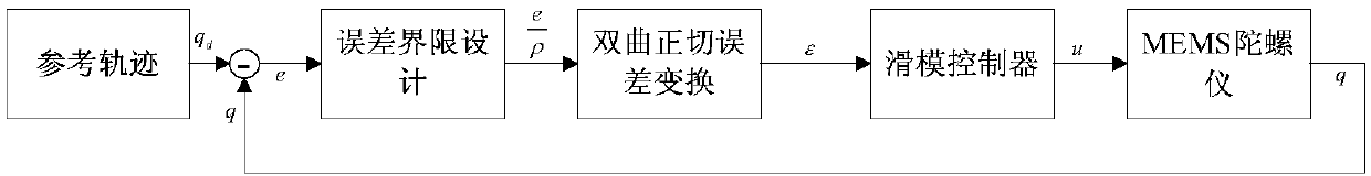
[0075] Such as figure 1 A micro-gyroscope sliding mode control method with error limitation shown includes the following steps:

[0076] 1) Establish a mathematical model of the micro gyroscope;

[0077] 2) The design of the error limit boundary;

[0078] 3) Equivalent error transformation;

[0079] 4) Sliding mode surface design using equivalent error;

[0080] 5) Design of control force;

[0081] 6) Proof of stability.

[0082] The mathematical model of the micro-gyroscope in the aforementioned step 1) is:

[0083]

[0084] in

[0085] Where x, y represent the displacement of the gyroscope in the direction of the XY axis, d xx d yy is the elastic coefficient of the spring in the direction of XY axis, k xx k yy is the damping coefficient in the direction of XY axis, d xy 、k xy is the coupling parameter caused by proce...


PUM


Abstract

The invention discloses a micro-gyroscope sliding mode control method with error limitation. The method comprises: step one, establishing a mathematical model of the micro gyroscope; step two, designing an error limiting boundary; step three, carrying out equivalent error transformation; step four, carrying out sliding mode surface designing by using an equivalent error; step five, carrying out control force designing; and step six, carrying out stability verification. According to the method disclosed by the invention, a needed error indicator curve can be designed manually before micro gyroscope controlling, so that the high quality response of the micro gyroscope system is ensured and the system stability is guaranteed.

Description

technical field [0001] The invention belongs to the technical field of automatic control systems, and in particular relates to a micro-gyroscope sliding mode control method with error limitation. Background technique [0002] Micro gyroscopes are very common sensors for measuring angular velocity and are used in many fields, such as navigation, mobile phones, aircraft models, and military guidance. A micro gyroscope is a device that can transfer energy from one axis to another. The principle is to use the Coriolis force (that is, the deflection force of the earth's rotation). The process of measuring angular velocity needs to add a vibration signal with stable amplitude and frequency to the driving shaft. The sensing axis and the driving shaft are in the same plane and perpendicular to each other. When there is an angular velocity input perpendicular to both the driving shaft and the sensing axis, the sensing axis The Coriolis force will be sensed, and the magnitude of the ...

Claims


Application Information

Patent Timeline
IPC IPC(8): G05B13/04
CPCG05B13/042
Inventor 卢成陈海龙郭云翔沈彦池张新松华亮
Owner NANTONG UNIVERSITY
Why Eureka
Try Eureka