
LED lamp control device and wading robot

A technology of LED lamps and control devices, applied in lighting devices, the use of semiconductor lamps, electrical components, etc., can solve problems such as poor adaptability, LED lamp burnout, and high power LED lamps, so as to achieve stable light emission and reduce burnout The probability of achieving the effect of linearly adjusting the brightness

Inactive Publication Date: 2018-07-20
SHENZHEN ZHENDI INFORMATION TECH CO LTD
View PDF0 Cites 1 Cited by
  • Summary
  • Abstract
  • Description
  • Claims
  • Application Information

AI Technical Summary

Problems solved by technology

The MOS tube unit only controls the LED light source according to the PWM signal sent by the control chip, which has poor adaptability and the luminescence of the LED light is unstable
When the duty ratio of the PWM signal is large, the power of the LED lamp is relatively large, and it is easy to burn out the LED lamp

Method used


Image

  • LED lamp control device and wading robot
  • LED lamp control device and wading robot
  • LED lamp control device and wading robot

Examples


Embodiment Construction

[0048]In order to make the purpose, technical solutions and advantages of the embodiments of the present invention clearer, the technical solutions of the present invention will be clearly and completely described below in conjunction with the accompanying drawings. Obviously, the described embodiments are part of the embodiments of the present invention, not all of them. the embodiment. The components of the embodiments of the invention generally described and illustrated in the figures herein may be arranged and designed in a variety of different configurations. Accordingly, the following detailed description of the embodiments of the invention provided in the accompanying drawings is not intended to limit the scope of the claimed invention, but merely represents selected embodiments of the invention. Based on the embodiments of the present invention, all other embodiments obtained by persons of ordinary skill in the art without making creative efforts belong to the protecti...


PUM


Abstract

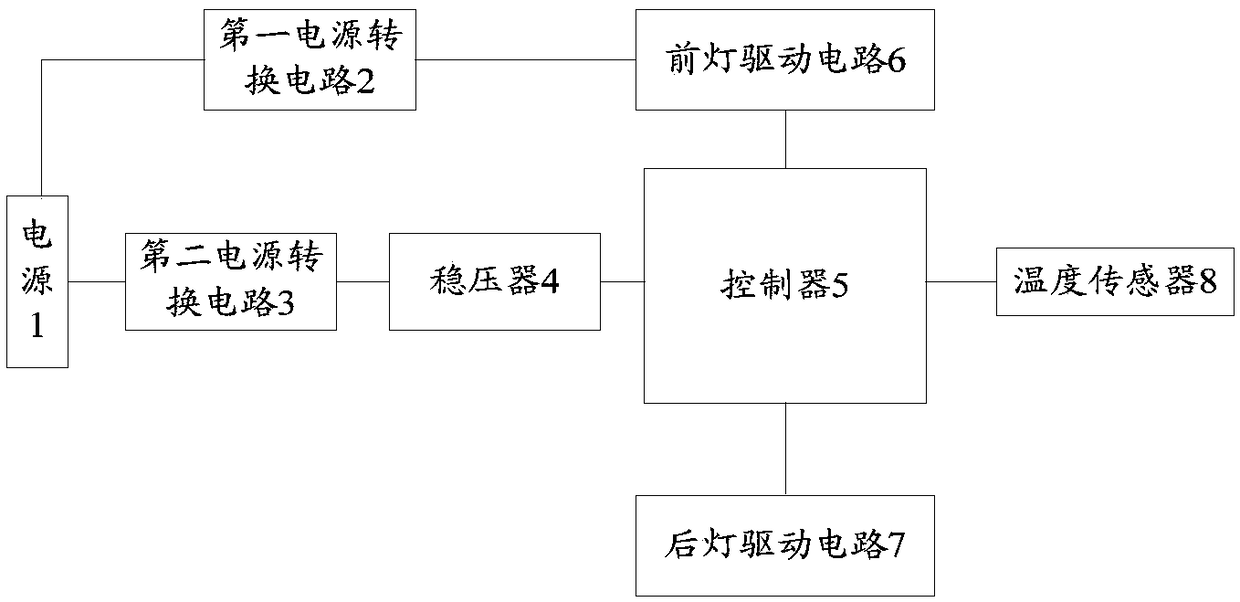
The invention provides an LED lamp control device and a wading robot, and belongs to the technical field of LED driving. According to the LED lamp control device and the wading robot provided by the embodiment of the invention, PWM control signals are supplied to a front lamp driving circuit and a rear lamp driving circuit by means of a controller. The front lamp driving circuit performs voltage self-adaptive adjustment on the brightness of a front lamp according to received PWM control signals. The rear lamp driving circuit performs voltage self-adaptive adjustment on the brightness of a rearlamp according to received PWM control signals. Therefore, the brightness of each LED lamp can be adjusted linearly, so that an LED light source is enabled to emit the light stably. The burnt probability of LED lamps is reduced.

Description

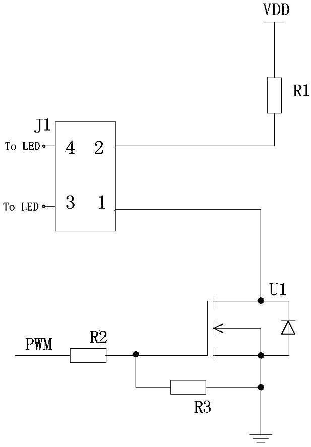
technical field [0001] The invention relates to the technical field of LED driving, in particular to an LED lamp control device and a wading robot. Background technique [0002] As an emerging industrial technology, LED lighting is constantly developing a wider range of applications. How to drive and control the LED light source is a key link in LED technology. At present, MOS tubes or triodes are usually used to control the work of LED light sources. [0003] figure 1 It is a kind of LED driving circuit in the prior art, such as figure 1 As shown, one pin of the LED light source interface J1 in the drive circuit is connected to the power supply VDD through a resistor, the other pin is connected to the drain of the MOS tube unit U1, the source of the MOS tube unit U1 is grounded, and connected to the power supply VDD through the resistor R3. The gate connection of the MOS transistor unit U1. The gate of the MOS transistor unit U1 is connected to the PWM output terminal o...

Claims


Application Information

Patent Timeline
IPC IPC(8): H05B33/08H05B44/00
CPCH05B45/10Y02B20/30
Inventor 不公告发明人
Owner SHENZHEN ZHENDI INFORMATION TECH CO LTD
Learn More