
Manual board discharging device for reflow soldering furnaces

A technology of reflow soldering furnace and board ejection device, which is applied in the direction of welding equipment, electrical components to assemble printed circuits, manufacturing tools, etc. It can solve problems such as circuit board burnout and printed circuit boards cannot be shaken out, so as to reduce wear and tear The effect of hand power

Inactive Publication Date: 2010-02-17
依工电子设备(苏州)有限公司
View PDF0 Cites 0 Cited by
  • Summary
  • Abstract
  • Description
  • Claims
  • Application Information

AI Technical Summary

Problems solved by technology

[0004] The purpose of the present invention is to provide a manual plate ejection device for reflow oven, which solves the problems in the

Method used


Image

  • Manual board discharging device for reflow soldering furnaces
  • Manual board discharging device for reflow soldering furnaces

Examples


Embodiment Construction

[0023] The above solution will be further described below in conjunction with specific embodiments. It should be understood that these examples are used to illustrate the present invention and not to limit the scope of the present invention. The implementation conditions used in the examples can be further adjusted according to the conditions of specific manufacturers, and the implementation conditions not indicated are usually the conditions in routine experiments.

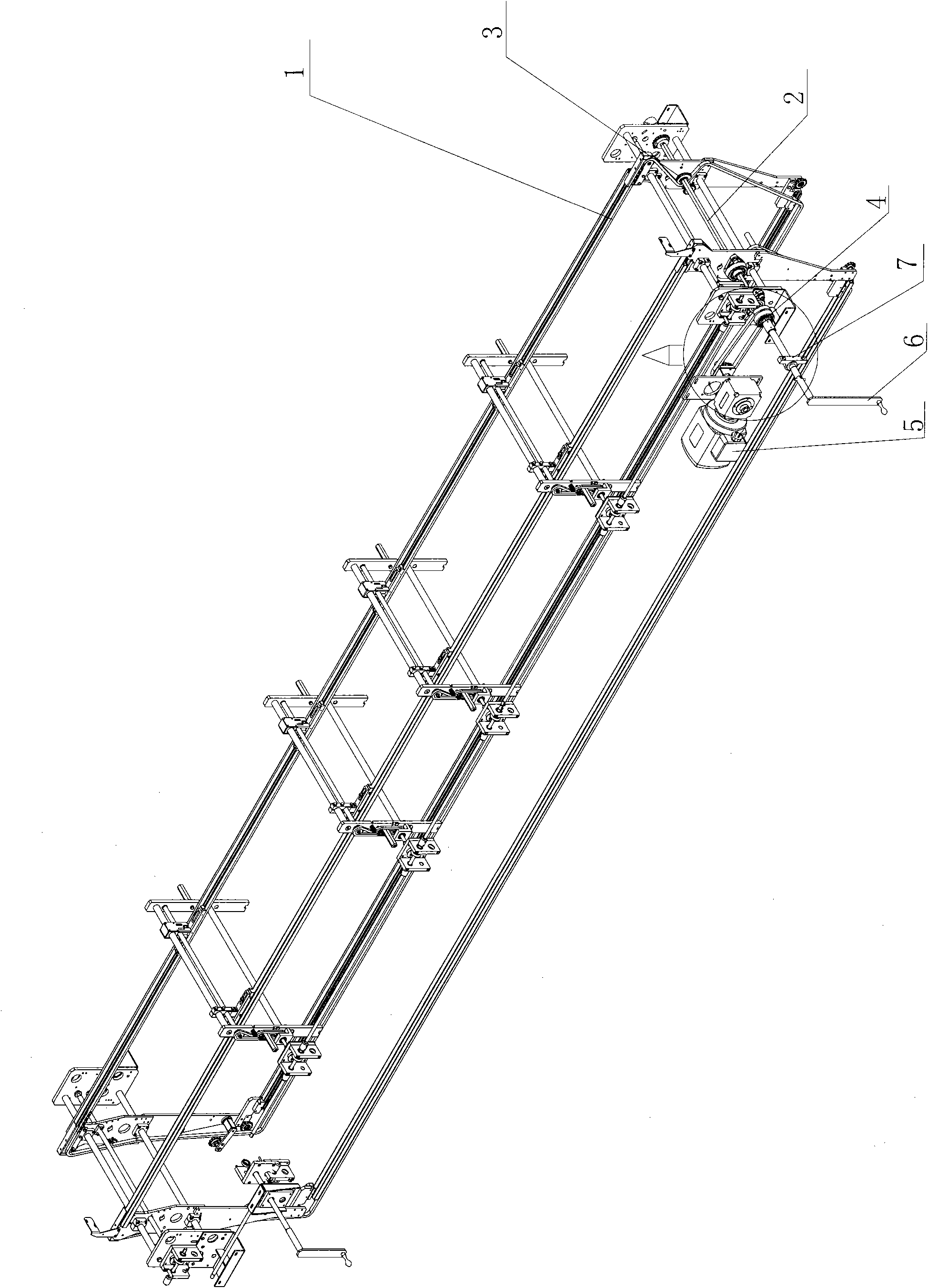
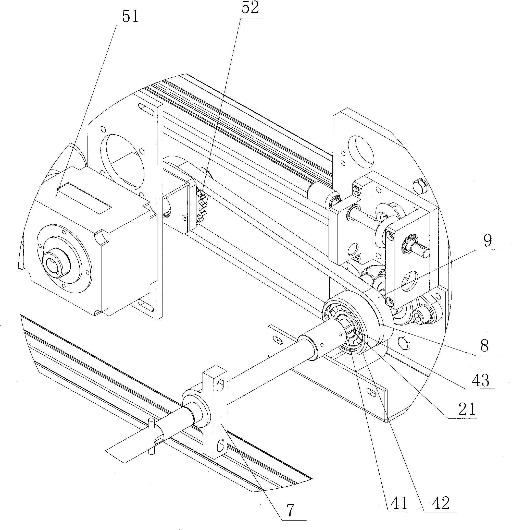
[0024] Examples such as Figure 1~2 , the reflow oven manual plate ejection device includes a conveyor chain 1 for conveying printed circuit boards, the conveyor chain is meshed with a sprocket 3 driven by a transmission shaft 2, and the outer side of the transmission shaft 2 is provided with a one-way bearing 4, so One side of the one-way bearing is provided with a reflow oven power unit 5, and the reflow oven power unit chain-drives the one-way bearing to drive the transmission shaft.

[0025] The power devic...


PUM


Abstract

The invention discloses a manual board discharging device for reflow soldering furnaces, which comprises a conveying chain (1) for conveying printed circuit boards, wherein the conveying chain mesheswith a sprocket (3) transmitted by a transmission shaft (2). The device is characterized in that a one-way bearing (4) is sheathed outside the transmission shaft (2), a reflow soldering power unit (5)is arranged on one side of the one-way bearing, and the reflow soldering power unit transmits the one-way bearing by the chain to drive the transmission shaft. The device can discharge boards by manual operation during power failure without being affected by the force of the retarder of the power unit.

Description

technical field [0001] The invention belongs to an emergency treatment device in the case of an accidental power failure of a reflow soldering furnace, and in particular relates to a device for manually ejecting boards after a reflow soldering furnace is powered off. Background technique [0002] Surface mount technology (Surface Mount Technology, SMT) is to directly paste and solder chip components or micro components suitable for surface mounting to the specified position on the surface of printed boards or other substrates without drilling holes for printed boards. on the assembly technology. After applying this technology, the product is compact in structure, high in assembly density, small in size, and light in weight. When double-sided mounting is used, the assembly density reaches 5.5-20 pieces / cm2, which is more than 5 times the assembly density of plug-in components. The area of ​​the printed board can be saved by more than 60% to 70%, and the weight can be reduced...

Claims


Application Information

Patent Timeline
IPC IPC(8): H05K3/34B23K1/008
Inventor 尚严辉
Owner 依工电子设备(苏州)有限公司
Learn More