a food processor

A food processing machine and circulating pipeline technology, applied in kitchen utensils, home utensils, applications, etc., can solve problems such as difficulty in entering and grinding, inability to enter into the grinding table to be ground, and complex structure of the circulating conditioner.

Active Publication Date: 2021-10-08
JOYOUNG CO LTD
View PDF8 Cites 0 Cited by
  • Summary
  • Abstract
  • Description
  • Claims
  • Application Information

AI Technical Summary

Problems solved by technology

[0003] In the above structure, since the grinding and crushing of the grinding disc is completed under the condition that the rotating speed is lower than 6000r / min, and a pressurizing mechanism needs to be set under the grinding disc to pressurize the slurry (the pressing mechanism is an upper and a lower conical disc or a pressurizing mechanism). pressure pump), so that the slurry enters the circulation pipeline and flows back into the container from the return port at the top of the circulation pipeline. Therefore, the above-mentioned circulation conditioning machine has a complex structure and high cost
And if there is no pressurizing mechanism, the above-mentioned conditioning machine will not be able to realize the circular cutting and grinding of the slurry inside and outside the circulation pipeline when making pulp
At the same time, the cutting blade is set on the top of the grinding disc. When the conditioning machine is working, the mixture of material and water flowing out from the return port is in a disordered state, and it is sprinkled on the cutting blade from all directions above. When the material is collided by the cutting blade, Therefore, it is difficult to enter into the grinding disc for grinding, and because the grinding disc is set at the bottom of the container, it is possible that the uncut large material particles cannot even enter during the whole pulping process. Grinded in the grinding disc
Therefore, the crushing efficiency of the conditioner is low, and it is possible to avoid large material particles after a long period of grinding

Method used


Image

  • a food processor
  • a food processor
  • a food processor

Examples


Embodiment 1

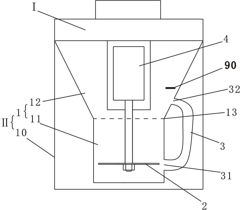
[0044] Such as figure 1 Shown is a schematic structural diagram of the first embodiment of the present invention. A food processing machine, the crushing device of the food processing machine includes a container 1, a crushing blade 2 arranged in the container 1 and a circulation pipeline 3 connecting the container up and down, the crushing blade 2 is driven by a motor 4, and the The circulation pipeline 3 is arranged outside the container, and the container 1 includes a crushing chamber 11 located at the bottom of the container, a return chamber 12 located above the crushing chamber 11, and a converging port 13 connecting the crushing chamber 11 and the return chamber 12. The blade 2 is located in the crushing chamber 11, and the gathering port 13 is arranged above the crushing blade 2, the inlet 31 of the circulation line is located in the crushing chamber 11, and the outlet 32 ​​of the circulation line is located in the return chamber 12 .

[0045] The food processing mac...

Embodiment 2

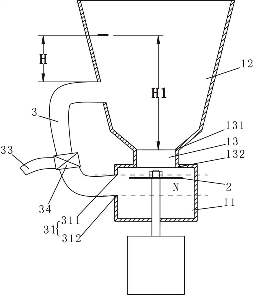
[0050] Such as figure 2 , image 3 Shown is a schematic structural diagram of the second embodiment of the present invention. The difference from Embodiment 1 is that the food processing machine in this embodiment has a structure with a motor under it, and the flow-gathering port 13 is tubular, and the flow-gathering port 13 has a water inlet 131 and a water outlet 132. The water inlet 131 is located in the return chamber 12 , and the water outlet 132 is located in the crushing chamber 11 . Moreover, the circulation pipeline 3 is provided with a slurry outlet 33 and a control valve 34, the slurry outlet 33 communicates with the circulation pipeline 3, and the control valve 34 is used to control the slurry outlet 33 to output the slurry, and to control The valve 34 is arranged between the slurry nozzle 33 and the circulation pipeline 3 . By setting the control valve 34 and the slurry outlet 33 , after the pulping is completed, the user can directly control the control valve...

Embodiment 3

[0058] Such as Figure 4 , Figure 5 , Figure 6 Shown is a schematic structural view of the third embodiment of the present invention. The difference from Embodiment 2 is that in this embodiment, the bottom of the recirculation cavity 12 has a converging portion 14 that protrudes toward the center of the container, and the top surface of the converging portion 14 is inclined downward relative to the horizontal plane. 14 The inclination angle α relative to the horizontal plane is generally less than 80°. Since the converging part 14 is in the shape of an inverted cone, the backflowing material and slurry can be collected, making it easier for the material to flow in from the converging port. At the same time, the top of the crushing chamber 11 is provided with a shielding part 15 that limits the material in the crushing chamber 11 (the shielding part 15 can further prevent the material from being ejected from the crushing chamber 11 after being collided by the crushing blad...


PUM


Abstract

The invention relates to small kitchen appliances, especially a food processing machine, which includes a container, and is characterized in that: the container includes a crushing chamber located at the bottom of the container, a return chamber arranged above the crushing chamber, and a The concentrating port of the pulverization chamber is provided with a pulverization blade, the capacity of the pulverization chamber is 22mL~380mL, the side wall of the recirculation chamber is provided with a water level marking line, and the pulverization chamber is arranged on the outside of the container. A circulation pipeline connected to the return chamber, the inlet of the circulation pipeline is located in the crushing chamber, the outlet of the circulation pipeline is located in the return chamber, and the outlet of the circulation pipeline is not set higher than the water level marking line. Compared with the prior art, the present invention has simple structure, low cost, can effectively reduce foam, can carry out concentrated crushing on materials, has high crushing efficiency, does not appear bean lump phenomenon, and is convenient to clean.

Description

technical field [0001] The invention relates to small kitchen appliances, in particular to a food processing machine. Background technique [0002] The patent number is "CN201220102774.1", and the utility model patent named "circulation conditioning machine" discloses a structure of a circulation conditioning machine. The bottom of the container of the conditioning machine is provided with a cutting blade and a grinding disc, and the side of the container is There is a circulation pipeline in the handle, and a pressurizing mechanism is set at the bottom of the grinding table to pressurize the slurry, so that the slurry enters the circulation pipeline, and then flows back into the container from the return port at the top of the circulation pipeline to realize the circular cutting of the material with grinding. [0003] In the above structure, since the grinding and crushing of the grinding disc is completed under the condition that the rotating speed is lower than 6000r / min...

Claims


Application Information

Patent Timeline
Patent Type & Authority Patents(China)
IPC IPC(8): A47J43/044A47J43/07
CPCA47J43/044A47J43/0705A47J43/0711A47J43/0727
Inventor 王旭宁张文凡薛领珑
Owner JOYOUNG CO LTD
Why Eureka
Try Eureka