Double-mold forming type pipe end forming machine

A molding machine and molding technology, applied in the directions of feeding devices, positioning devices, storage devices, etc., can solve the problems of not meeting production requirements, unable to achieve molding size, troublesome to replace pipe end molding machines, etc., to achieve the effect of improving efficiency

Inactive Publication Date: 2018-07-24
张家港市蓝田管业设备有限公司
0 Cites 1 Cited by

AI-Extracted Technical Summary

Problems solved by technology

[0002] When the existing pipe fittings are formed by the mold, the required forming size is often not achieved in one-tim...

Method used

[0024] The contracted state and the extended state of the third pneumatic cylinder are respectively the positions of the two forming molds when they are working, thus avoiding the situation that the forming mold is not aligned with the pipe fitting due to the extension of the third pneumatic cylinder.
[0026] The sliding structure is preferably adopted, which is...

Abstract

The invention discloses a double-mold forming type pipe end forming machine. The double-mold forming type pipe end forming machine comprises a forming tool, a clamping tool and a working table face; the forming tool comprises a second bracket fixedly installed on the working table face, a second pneumatic cylinder fixedly installed on the second bracket, a sliding table slidably installed on the second bracket, a third pneumatic cylinder fixedly installed on the second bracket and a sliding block slidably installed on one side of the sliding table; and the side, deviating from the sliding block, of the sliding table is fixedly installed at the output end of the second pneumatic cylinder, the output end of the third pneumatic cylinder is fixedly installed on one side of the sliding block, and a first forming mold and a second forming mold are arranged on the side, deviating from the sliding table, of the sliding block side by side. The double-mold forming type pipe end forming machine has the advantages that the forming tool of a same pipe end forming machine is provided with two different forming molds, a pipe only needs to be clamped one time, secondary forming on a port of the pipe is achieved by moving the forming mold, and the efficiency is improved.

Application Domain

Metal-working feeding devicesPositioning devices +1

Technology Topic

Pneumatic cylinderEngineering +3

Image

  • Double-mold forming type pipe end forming machine
  • Double-mold forming type pipe end forming machine

Examples

  • Experimental program(1)

Example Embodiment

[0018] The technical solutions in the embodiments of the present invention will be described in detail below with reference to the drawings in the embodiments of the present invention. Obviously, the described embodiments are only a part of the embodiments of the present invention, rather than all the embodiments. Based on the embodiments of the present invention, all other embodiments obtained by those of ordinary skill in the art without creative work shall fall within the protection scope of the present invention.
[0019] In the description of the present invention, it should be noted that the terms "center", "upper", "lower", "left", "right", "vertical", "horizontal", "inner", "outer", etc. The indicated orientation or positional relationship is based on the orientation or positional relationship shown in the drawings, which is only for the convenience of describing the present invention and simplifying the description, rather than indicating or implying that the pointed device or element must have a specific orientation or a specific orientation. The structure and operation cannot therefore be understood as a limitation of the present invention. In addition, the terms "first", "second", and "third" are only used for descriptive purposes, and cannot be understood as indicating or implying relative importance.
[0020] In the description of the present invention, it should be noted that the terms "installed", "connected" and "connected" should be understood in a broad sense, unless otherwise clearly specified and limited. For example, they can be fixed or detachable. Connected or integrally connected; it can be a mechanical connection or an electrical connection; it can be directly connected or indirectly connected through an intermediate medium, and it can be the internal communication between two components. For those of ordinary skill in the art, the specific meaning of the above-mentioned terms in the present invention can be understood in specific situations.
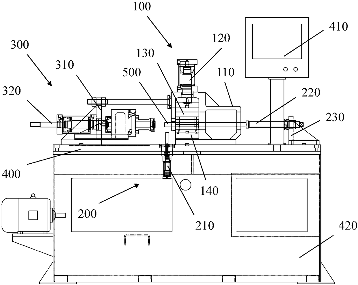
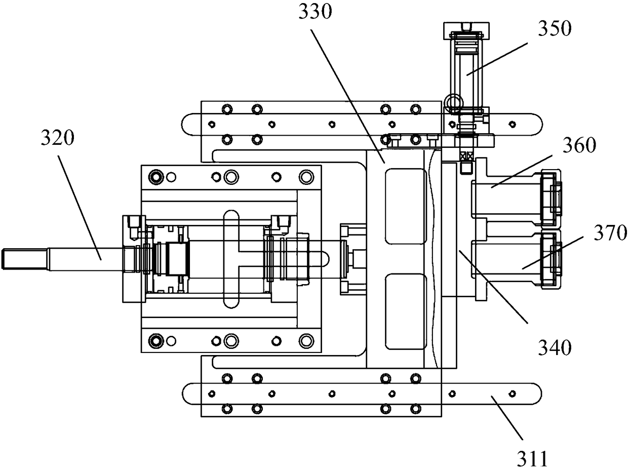
[0021] Combine Figure 1-2 As shown, the dual-mold forming tube end forming machine includes a forming tool 300, a clamping tool 100, and a work surface 400. The clamping tool 100 includes a first bracket 110 fixedly installed on the work surface 400 and a first bracket 110 fixedly installed on the first bracket 110. The top first pneumatic cylinder 120, the upper clamping block 130 fixedly installed at the output end of the first pneumatic cylinder 120, the lower clamping block 140 corresponding to the upper clamping block 130, the lower clamping block 140 is fixedly installed on the first bracket 110 , The upper clamping block 130 and the lower clamping block 140 clamp the pipe 500, the bottom surface of the upper clamping block 130 and the top surface of the lower clamping block 140 are respectively attached to the pipe 500, and the forming tool 300 includes a second fixed installation on the working table 400 The bracket 310, the second pneumatic cylinder 320 fixedly installed on the second bracket 310, the sliding table 330 slidably installed on the second bracket 310, the third pneumatic cylinder 350 fixedly installed on the second bracket 310, and the sliding table 330 The side of the sliding block 340, the side of the sliding table 330 away from the sliding block 340 is fixedly installed at the output end of the second pneumatic cylinder 320, the moving direction of the sliding table 330 is parallel to the axial direction of the pipe 500, and the moving direction of the sliding block 340 is perpendicular to the sliding table 330. In the direction, the output end of the third pneumatic cylinder 350 is fixedly installed on the side of the sliding block 340, and the side of the sliding block 340 facing away from the sliding table 330 is provided with a first forming mold 370 and a second forming mold 360 side by side.
[0022] The pipe is clamped by the two clamping blocks of the clamping tool, and one of the two forming molds is selected by the third pneumatic cylinder, and then the mold is pushed into the pipe fitting port through the second pneumatic cylinder to form the pipe fitting port, and then the third pneumatic cylinder The second mold is selected by shrinking or extending to realize the secondary molding of the once-molded pipe, and finally obtain the required size, which improves the efficiency.
[0023] Furthermore, when the output end of the third pneumatic cylinder 350 contracts, the first forming mold 370 faces the pipe 500, and when the output end of the third pneumatic cylinder 350 extends, the second forming mold 360 faces the pipe 500.
[0024] The contracted state and the extended state of the third pneumatic cylinder are respectively the positions of the two forming molds when they are working, which avoids the misalignment of the mold and the pipe due to the extension of the third pneumatic cylinder.
[0025] Furthermore, two sides of the second bracket 310 are respectively provided with sliding rails 311, and both sides of the sliding table 330 are slidably installed on the sliding rails 311.
[0026] The sliding structure is preferably adopted, which is simple and practical, but other structures such as sliding grooves can also be used, which should fall within the scope of the present application.
[0027] Further, the sliding table 330 is provided with a sliding groove (not shown in the figure) on one side of the sliding block 340, and the sliding block 340 is slidably installed in the sliding groove.
[0028] The sliding structure is preferably adopted, which is simple and practical, but other structures such as sliding rails can also be used, which should fall within the scope of this application.
[0029] Further, it also includes a positioning tool 200. The positioning tool 200 includes a fourth pneumatic cylinder 210 fixedly installed below the work surface 400, the output end of the fourth pneumatic cylinder 210 protruding from the work surface 400, and the positioning pipe 500 of the fourth pneumatic cylinder 210 is convex Extend the length of the clamping tooling.
[0030] Accurately locate the length of the tube projecting from the clamping fixture.
[0031] Further, the positioning tool 200 further includes a positioning screw 220. One end of the positioning screw 220 abuts against the end of the pipe 500, and the other end of the positioning screw 220 is connected to a vertical rod 230 through screw rotation, and the vertical rod 230 is fixedly installed on the work surface 400 .
[0032] After the pipe fittings of the same specification are positioned by the first pneumatic cylinder for the first time, the screw can be used for positioning afterwards, and the positioning screw can be directly resisted, which is convenient and quick.
[0033] Furthermore, the positioning screw 220 is provided with a circular groove (not shown in the figure) for accommodating the pipe 500 at one end that is against the pipe 500.
[0034] Facilitate the positioning of pipe fittings.
[0035] Further, a computer operation box 410 is installed on the work surface 400, and the computer operation box 410 is located at one end of the work surface 400.
[0036] Furthermore, the work surface 400 is fixedly supported on the body 420.
[0037] It should be noted that in this article, relational terms such as first and second are only used to distinguish one entity or operation from another entity or operation, and do not necessarily require or imply one of these entities or operations. There is any such actual relationship or order between. Moreover, the terms "include", "include" or any other variants thereof are intended to cover non-exclusive inclusion, so that a process, method, article, or device that includes a series of elements includes not only those elements, but also includes Other elements of, or also include elements inherent to this process, method, article or equipment. If there are no more restrictions, the element defined by the sentence "including a..." does not exclude the existence of other same elements in the process, method, article, or equipment including the element.
[0038] The above are only specific implementations of this application. It should be pointed out that for those of ordinary skill in the art, without departing from the principles of this application, several improvements and modifications can be made, and these improvements and modifications are also Should be regarded as the scope of protection of this application.

PUM

no PUM

Description & Claims & Application Information

We can also present the details of the Description, Claims and Application information to help users get a comprehensive understanding of the technical details of the patent, such as background art, summary of invention, brief description of drawings, description of embodiments, and other original content. On the other hand, users can also determine the specific scope of protection of the technology through the list of claims; as well as understand the changes in the life cycle of the technology with the presentation of the patent timeline. Login to view more.

Similar technology patents

Compositing Windowing System

InactiveUS20100058229A1minimal costimprove efficiency
Owner:QUALCOMM INC

Control circuit and method for a buck-boost power converter

ActiveUS20110074373A1improve efficiencyminimize output ripple
Owner:RICHTEK TECH

Classification and recommendation of technical efficacy words

  • Improve efficiency
Why Eureka
Try Eureka