Automatic stamping machine

An automatic stamping machine and movement technology, applied in the field of stamping machines, can solve the problems of not necessarily accurate stamping position, cumbersome operation process, inconvenient light desktop office, etc., to achieve convenient photo identification and ensure personal safety , Office convenient and labor-saving effect

Pending Publication Date: 2018-07-24
SHENZHEN MAXVISION TECH
View PDF12 Cites 7 Cited by
  • Summary
  • Abstract
  • Description
  • Claims
  • Application Information

AI Technical Summary

Problems solved by technology

[0002] The general stamping machines on the market basically only have a simple vertical stamping function, that is, a cylinder drives the stamp fixture to move straight up and down to stamp, without positioning and identification functions, without positioning functions, that is, without reference positions, so Even if the manual pays special attention to placing the documents every time, it may not be placed in place, resulting in the location of the stamp is not necessarily accurate; without the recognition function, it is impossible to identify whether the position where the document needs to be stamped has been stamped before stamping, and it is also It is not possible to identify whether the stamp is accurate, etc. If you need to add the stamp positioning recognition function, you need to add another device or manual operation
Adding equipment will increase the cost, and it is inconvenient to light desktop office; completely manual operation will make the operation process cumbersome and labor-intensive

Method used


Image

  • Automatic stamping machine
  • Automatic stamping machine
  • Automatic stamping machine

Examples


Embodiment Construction

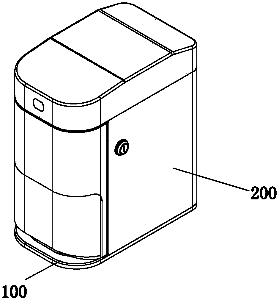
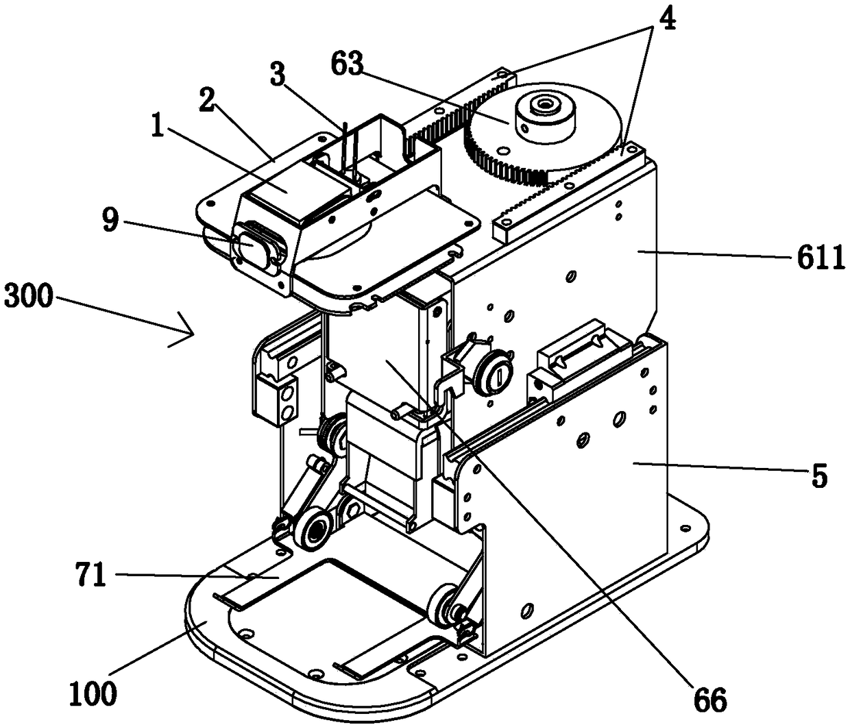
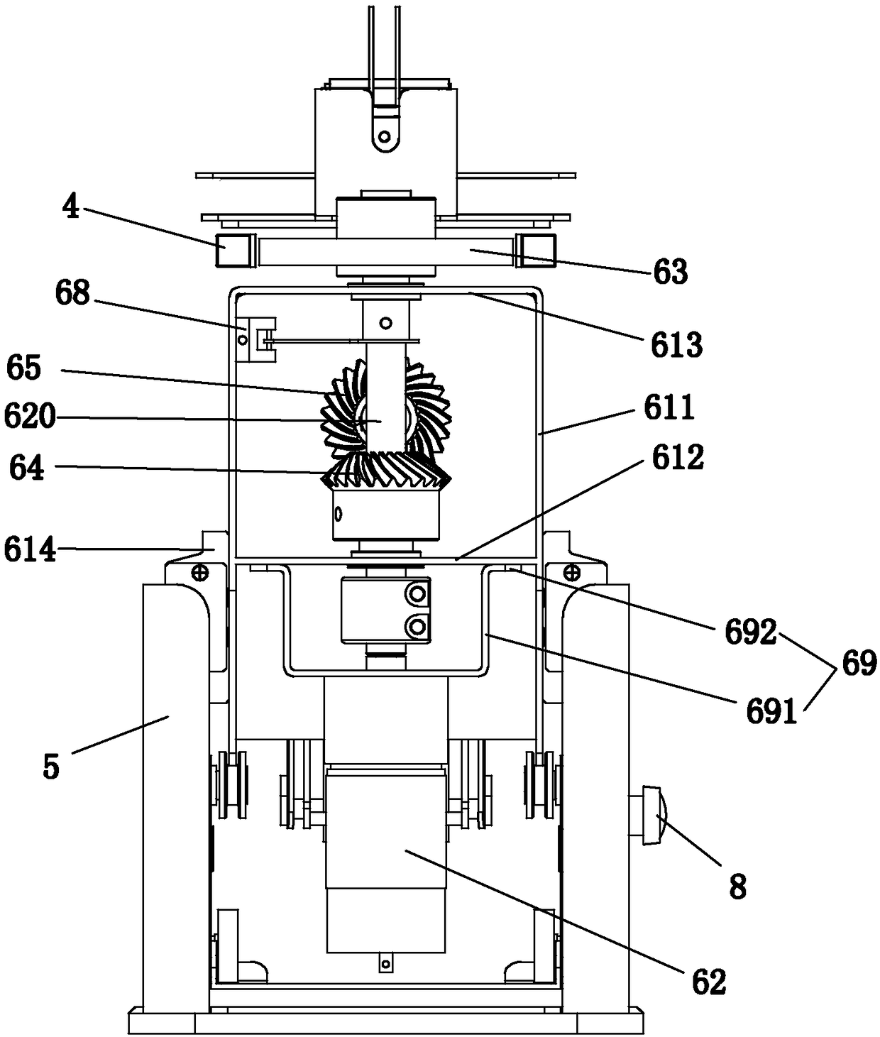
[0024] Such as figure 1 , 2 , 3, 4, 5, 6, and 7, the automatic stamping machine of the present invention is used for stamping documents, and the automatic stamping machine includes a base plate 100, a housing 200 fixedly connected to the base plate 100, a set The functional part 300 in the space enclosed by the base plate 100 and the housing 200 has a gap between the lower end of the front side of the housing 200 and the base plate 100 , and the functional part 300 includes a A camera 1 on the side, a main control board 2 for control, analysis and identification, a positioning cursor 3 arranged on the main control board 2, two left and right racks 4 fixedly connected to the upper rear side of the housing 200, Two fixed plates 5 respectively connected to the left and right sides of the bottom plate 100, the movement 6 connected to the left and right fixed plates 5 movable back and forth, can be pressed down with the movement of the movement 6 forward and backward. The left an...


PUM


Abstract

The invention discloses an automatic stamping machine. The automatic stamping machine comprises a bottom plate, a shell fixedly connected to the bottom plate, and a function part arranged in a space defined by the bottom plate and the shell; a gap is arranged between the lower end of the front side of the shell and the bottom plate, the function part comprises a camera connected to the front sideabove the shell, a master control board for analyzing and recognizing, a positioning cursor arranged on the master control board, two fixed plates connected to the left side and the right side of thebottom plate, a machine core movably connected to the left and right fixed plates in a front and back manner, and a compressing mechanism for compressing a stamped document; the machine core comprisesa stamp clamp which can move up and down along with front and back moving of the machine core, the document is inserted below the pressing plate from the gap, the positioning cursor positions the stamped area, the compressing device compresses the document, the machine core moves front and back to drive the stamp clamp to move up and down for stamping, the camera photographing the document stamped area and transmits the photo to the master control board, and the master control board carries out recognizing.

Description

technical field [0001] The invention relates to office equipment, in particular to a stamping machine. Background technique [0002] The general stamping machines on the market basically only have a simple vertical stamping function, that is, a cylinder drives the stamp fixture to move straight up and down to stamp, without positioning and identification functions, without positioning functions, that is, without reference positions, so Even if the manual pays special attention to placing the documents every time, it may not be placed in place, resulting in the location of the stamp is not necessarily accurate; without the recognition function, it is impossible to identify whether the position where the document needs to be stamped has been stamped before stamping, and it is also It is not possible to identify whether the seal is accurate after stamping. If you need to add the stamp positioning recognition function, you need to add another device or manual operation. Adding ...

Claims


Application Information

Patent Timeline
Patent Type & Authority Applications(China)
IPC IPC(8): B41K3/04B41K3/62
CPCB41K3/04B41K3/62
Inventor 关庆佳赖时伍王和平瞿磊范福川
Owner SHENZHEN MAXVISION TECH
Why Eureka
Try Eureka