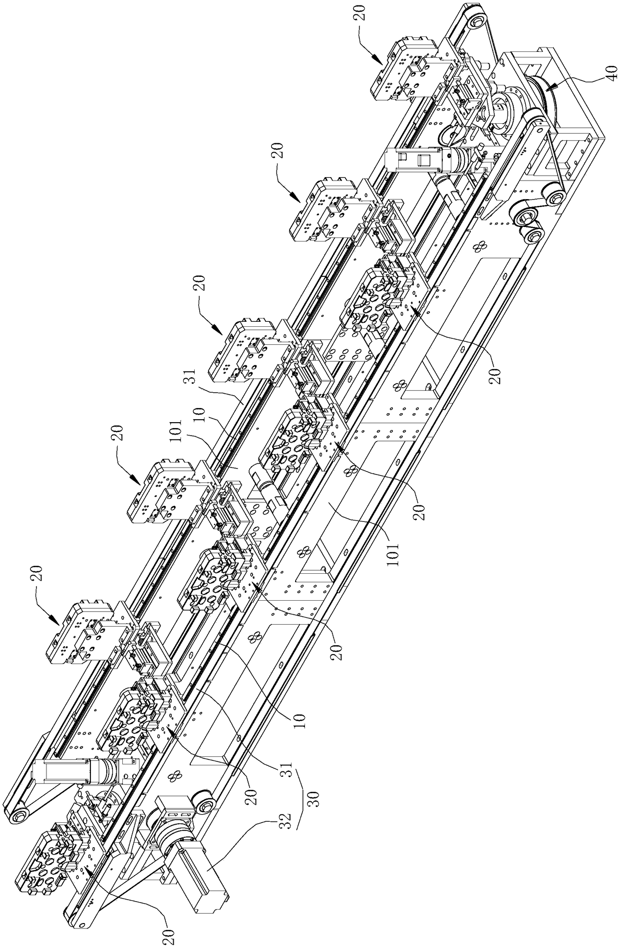
Plane type jig assembly rotating flow channel device

A rotary device and rotary flow technology, applied in the field of automation, can solve problems such as high cost, affecting assembly speed, and low efficiency, and achieve the effects of fast rotary speed, easy operation, and accurate positioning

Pending Publication Date: 2018-07-24
SHENZHEN SHIZONG AUTOMATION EQUIP CO LTD
View PDF0 Cites 8 Cited by
  • Summary
  • Abstract
  • Description
  • Claims
  • Application Information

AI Technical Summary

Problems solved by technology

[0003] The existing assembly lines are generally divided into linear or circular. The linear assembly line has the advantage of faster flow speed, but the existing linear assembly line usually only allows the jig to flow from one e

Method used


Image

  • Plane type jig assembly rotating flow channel device
  • Plane type jig assembly rotating flow channel device
  • Plane type jig assembly rotating flow channel device

Examples


Embodiment Construction

[0032] Embodiments of the present invention are described in detail below, examples of which are shown in the drawings, wherein the same or similar reference numerals designate the same or similar elements or elements having the same or similar functions throughout. The embodiments described below by referring to the accompanying drawings are exemplary and are intended to explain the present invention, but cannot be construed as limitations to the present invention. Based on the embodiments in the present invention, those skilled in the art do not make creative work premise All other embodiments obtained below all belong to the protection scope of the present invention.

[0033] In describing the present invention, it should be understood that the terms "center", "longitudinal", "transverse", "length", "width", "thickness", "upper", "lower", "front", " Back", "Left", "Right", "Vertical", "Horizontal", "Top", "Bottom", "Inner", "Outer", "Clockwise", "Counterclockwise", "Axial",...


PUM


Abstract

The invention discloses a plane type jig assembly rotating flow channel device. The plane type jig assembly rotating flow channel device comprises a base frame and rotating devices at the two ends ofthe base frame; the base frame is provided with two parallel fixing slide rails in a left-right extending manner; each rotating device comprises a rotating mechanism and a rotating platform; a transferring slide rail is arranged on each rotating platform; the rotating platforms are driven by the rotating mechanisms to be capable of rotating between a first position and a second position; when therotating platforms are located at the first position, the transferring slide rails are in butt joint with one of the fixing slide rails; and when the rotating platforms rotate to the second position,the transferring slide rails are in butt joint with another fixing slide rail. According to the technical scheme, due to the fact that the two ends of the base frame are each provided with the corresponding rotating device, a jig assembly on one fixing slide rail can move to the other fixing slide rail after rotating by 180 degrees through the rotating devices, it is achieved that the jig assemblyrotates on the two fixing slide rails cyclically, the rotating speed is high, the rotating effect is high, positioning is accurate, and the front side of the jig assembly faces the outer side of thebase frame all the time.

Description

technical field [0001] The invention relates to the technical field of automation, in particular to a rotary channel device for a planar jig assembly. Background technique [0002] Fixture rotary runner, also known as assembly line or assembly line, is an industrial production method, which means that each production unit only focuses on processing a certain segment of work to improve work efficiency and output. The assembly line has high scalability, and the conveying volume, conveying speed, assembly station, auxiliary parts, etc. can be designed according to the demand. [0003] The existing assembly lines are generally divided into linear or circular. The linear assembly line has the advantage of faster flow speed, but the existing linear assembly line usually only allows the jig to flow from one end to the other end, and cannot circulate. Low, which affects the assembly speed; while the circular assembly line can be circulated, but it occupies a large space, and the st...

Claims


Application Information

Patent Timeline
IPC IPC(8): B65G37/00
CPCB65G37/00
Inventor 高超马爽柳在贤
Owner SHENZHEN SHIZONG AUTOMATION EQUIP CO LTD
Why Eureka
Try Eureka