
Device for horizontally and axially conveying steel wire

An axial and steel wire technology, applied in the direction of transportation and packaging, delivery of filamentous materials, thin material processing, etc., can solve problems such as messy wires, unsuitable for high-strength steel wire transportation, and inability to process steel wires, so as to prevent falling off and fast The effect of conveying and preventing the wire from falling off

Inactive Publication Date: 2018-07-24
JIANGSU LIWEI SHEARING & BENDING MACHINE
View PDF0 Cites 0 Cited by
  • Summary
  • Abstract
  • Description
  • Claims
  • Application Information

AI Technical Summary

Problems solved by technology

Using the pallet axial conveying method, the steel wire is released from the axial direction of the steel wire bundle, and the steel wire bundle does not rotate with the traction force. When using the pallet axial conveying device, the steel wire bundle is tilted 10 degrees relative to the horizontal plane to release the general low-carbon steel wire sequentially. Therefore, it is suitable for fast weaving, but when high-strength steel wire needs to be conveyed quickly from the horizontal direction, because high-strength steel wire has stronger elasticity than low-carbon steel wire, the initial traction will make more steel wire axially fall off the pallet in advance , resulting in messy wires, so that the steel wires cannot be processed normally. Therefore, the existing pallet axial conveying device is not suitable for conveying high-strength steel wires, and the scope of use has certain limitations.

Method used


Image

  • Device for horizontally and axially conveying steel wire

Examples


Embodiment Construction

[0011] The following will clearly and completely describe the technical solutions in the embodiments of the present invention with reference to the accompanying drawings in the embodiments of the present invention. Obviously, the described embodiments are only some, not all, embodiments of the present invention. Based on the embodiments of the present invention, all other embodiments obtained by persons of ordinary skill in the art without making creative efforts belong to the protection scope of the present invention.

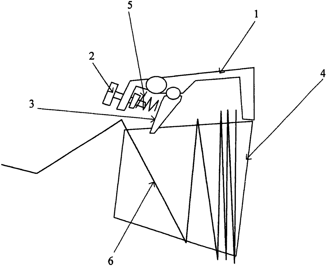
[0012] Such as figure 1 As shown, a device for horizontally and axially conveying steel wires includes a cantilever 1 connected to a tray 4 and an adjustment device. A stop rod 3 is movably connected to the cantilever 1. The movable end of the stop rod 3 is elastically connected to the adjustment device. The stop rod The lower part of the 3 is provided with a pallet 4 for suiting the steel wire bundles, the retaining rod 3 extends into the inner circle of the ...


PUM


Abstract

The invention discloses a device for horizontally and axially conveying a steel wire. The device for horizontally and axially conveying the steel wire is mainly used for weaving of a slope protectivenet. The device for horizontally and axially conveying the steel wire comprises a cantilever connected to a tray and an adjusting device. Stop rods are movably connected to the cantilever. The movingends of the stop rods are elastically connected with the adjusting device. The lower portions of the stop rods are provided with the tray used for arranging a steel wire bundle in a sleeved manner. The ends of the stop rods extend into an inner circle of the annular steel wire bundle. The tray is in a circular truncated cone shape, so that the tray is conveniently used for sleeved arrangement of aformed steel wire ring. The multiple stop rods cooperate with the tray, so that cooperation between the stop rods and the tray is tighter, and the steel wire is more effectively prevented from falling. The adjusting device comprises adjusting rods connected with the cantilever and springs which are arranged on the adjusting rods and connected with the stop rods, the adjusting device enables the stop rods to achieve rapid resetting, the steel wire bundle is prevented from falling, and adjustment is convenient. Under the cooperation of the stop rods and the tray, a follow-up steel wire is prevented from falling in advance, and rapid conveyance of the steel wire is achieved.

Description

technical field [0001] The invention relates to a steel wire conveying device, in particular to a device for weaving side slope protection nets, capable of conveying low-carbon steel wires and high-strength steel wires in a horizontal axial direction. Background technique [0002] The steel wire conveying device is generally used in the weaving process of grid mesh, that is, steel wire mesh. Its function is to continuously provide the whole plate of steel wire for the weaving machine, and no related reports have been found in the existing literature. Existing steel wire conveying devices can be divided into two types: pallet axial conveying and pallet plane conveying. The pallet plane conveying method has high requirements on the damping setting of the steel wire bundle rotation, is not suitable for fast weaving, has low work efficiency, and is not suitable for popularization and application. Using the pallet axial conveying method, the steel wire is released from the axial...

Claims


Application Information

Patent Timeline
Patent Type & Authority Applications(China)
IPC IPC(8): B65H51/18
CPCB65H51/18B65H2701/36
Inventor 不公告发明人
Owner JIANGSU LIWEI SHEARING & BENDING MACHINE
Learn More