Anti-seismic fixing structure for ancient building corridor bridge and use method thereof

A technology for fixing structures and ancient buildings, applied in buildings, bridges, bridge parts, etc., can solve the problems of restricting the development of corridor bridge business models, the overall structural strength of corridor bridges is not high, and the strength of building structures is not high, so as to achieve flexible and novel structural design , The device can withstand high strength and good seismic effect

Active Publication Date: 2018-07-24
CHANGSHU ANCIENT STYLE GARDEN CONSTR CORP
6 Cites 0 Cited by

AI-Extracted Technical Summary

Problems solved by technology

[0003] However, due to the unreasonable structural design of the existing covered bridges, the covered bridges have the problems of low overall structural strength, inconvenient transportation, and single function, which largely limits the...

Method used

Wherein, the left side of connector 1 is provided with the first threaded hole 101, and the left support bar 2 is provided with the external thread section that matches with the first threaded hole 101, and the right side of connector 1 is provided with the second threaded hole 102, and the right support rod 4 is provided with an external thread segment matching the second threaded hole 102, the front side of the connector 1 is provided with a third threaded hole 103, and both ends of the connecting rod 3 are provided with a third threaded hole 103 matched external thread section, through this setting can be connected by screwing, so that the entire fixed structure is easy to disassemble, and the convenience of installation is improved. The contact between the slider 17 and the chute 18 is coated with wear-resistant Layer, and the inner cavity of the chute 18 is coated with a corrosion-resistant layer, through this arrangement can reduce the friction between the slider 17 and the chute 18, which i...

Abstract

The invention discloses an anti-seismic fixing structure for an ancient building corridor bridge in the technical field of anti-seismic fixing. Ejecting blocks are arranged at the tops of bases; U-shaped plates are arranged at the tops of the ejecting blocks; elastic telescopic rods and second rigid springs are arranged at the tops of the U-shaped plates; the second rigid springs are arranged in the outer edge directions of the elastic telescopic rods; the tops of the elastic telescopic rods and the second rigid springs are connected with second fixing blocks; second fixing lining plates are arranged at the tops of the second fixing blocks; two groups of guide frames with same structures are arranged at the bottoms of the second fixing lining plates; connecting blocks are arranged on one sides, far away from the second rigid springs, of the U-shaped plates; sliding grooves are formed in cavities of the guide frames; the other ends of the elastic supporting rods are connected with mounting plates; and first rigid springs are arranged at the outer edges of the elastic supporting rods. The anti-seismic fixing structure for the ancient building corridor bridge has the advantages that the structural design is reasonable, the bearable strength is higher, the anti-seismic effect is good, the mounting is firm and the anti-seismic fixing problem of the ancient building corridor bridge is very well solved.

Application Domain

Bridge applicationsBridge structural details

Technology Topic

EngineeringStructural engineering +3

Image

  • Anti-seismic fixing structure for ancient building corridor bridge and use method thereof
  • Anti-seismic fixing structure for ancient building corridor bridge and use method thereof
  • Anti-seismic fixing structure for ancient building corridor bridge and use method thereof

Examples

  • Experimental program(1)

Example Embodiment

[0027] The technical solutions in the embodiments of the present invention will be clearly and completely described below in conjunction with the accompanying drawings in the embodiments of the present invention. Obviously, the described embodiments are only a part of the embodiments of the present invention, rather than all the embodiments. Based on the embodiments of the present invention, all other embodiments obtained by those of ordinary skill in the art without creative work shall fall within the protection scope of the present invention.
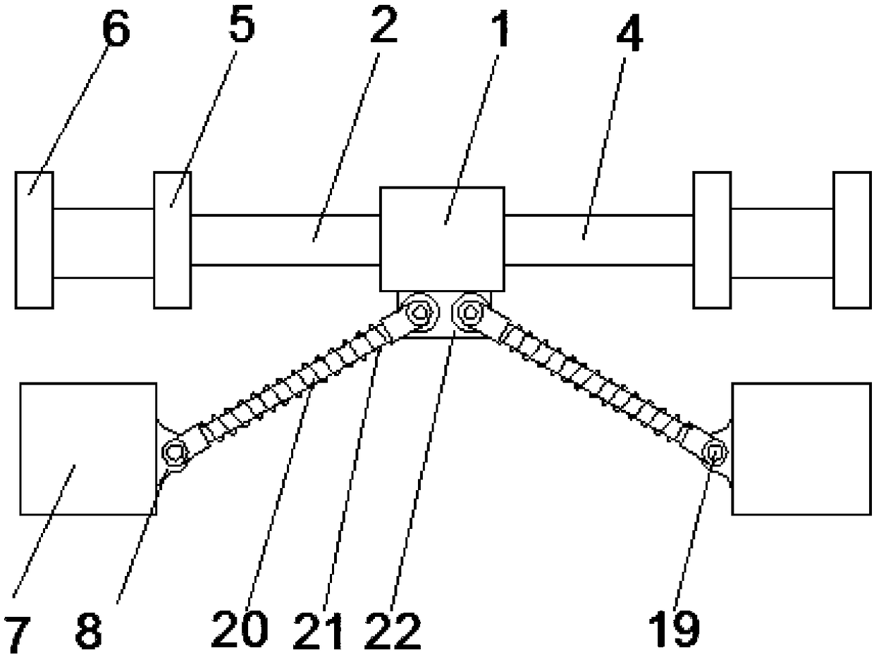
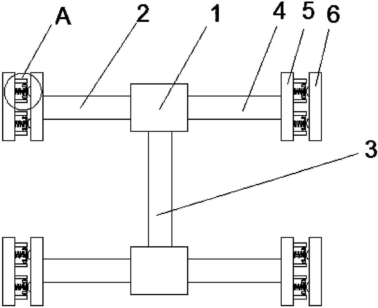
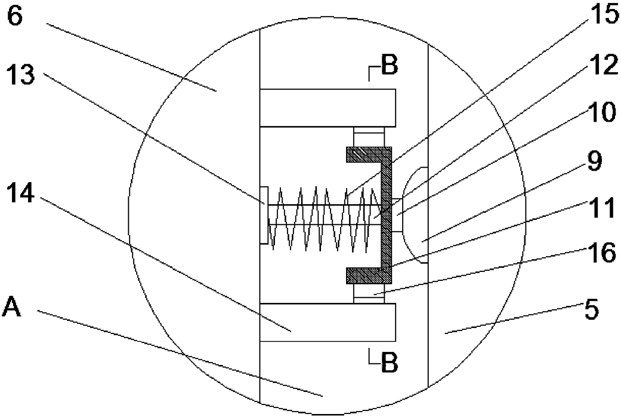
[0028] See Figure 1-5 , The present invention provides a technical solution: an earthquake-resistant fixed structure for ancient building gallery bridges, including a connector 1. The left and right sides of the connector 1 are respectively provided with a left support rod 2 and a right support rod 4, and the connector A connecting rod 3 is provided at the bottom of 1, and both ends of the connecting rod 3 are connected to the connector 1. The ends of the left support rod 2 and the right support rod 4 away from the connector 1 are both provided with a first fixing pad 5, a first fixing pad The top surface of the plate 5 is provided with a base 9, the top of the base 9 is provided with a top block 10, the top of the top block 10 is provided with a U-shaped plate 11, and the top of the U-shaped plate 11 is provided with an elastic telescopic rod 12 and a second rigid spring 15. And the second rigid spring 15 is arranged in the direction of the outer edge of the elastic telescopic rod 12, the top of the elastic telescopic rod 12 and the second rigid spring 15 are connected to the second fixed block 13, and the top of the second fixed block 13 is provided with a second fixed backing plate 6, The bottom of the second fixed backing plate 6 is provided with two sets of guide frames 14 with the same structure, and the guide frames 14 are provided on both sides of the second fixed block 13, and the U-shaped plate 11 is provided with a connection on the side away from the second rigid spring 15 Block 16, the inner cavity of the guide frame 14 is provided with a sliding groove 18, the connecting block 16 is provided with a sliding block 17 that cooperates with the sliding groove 18, and the bottom of the connector 1 is provided with a first fixing block 22, the first fixing Both the left and right sides of the block 22 are provided with elastic support rods 20, and the elastic support rods 20 are connected to the first fixing block 22 by connecting bolts 19, the other end of the elastic support rods 20 is connected to the mounting plate 8, and the mounting plate 8 is arranged on the fixing seat 7 On one side wall close to the elastic support rod 20 and connected by a connecting bolt 19, the outer edge of the elastic support rod 20 is provided with a first rigid spring 21.
[0029] Wherein, the left side of the connector 1 is provided with a first threaded hole 101, and the left support rod 2 is provided with an external threaded section that matches the first threaded hole 101, and the right side of the connector 1 is provided with a second threaded hole 102, and The right support rod 4 is provided with an external thread section that matches the second threaded hole 102, the front side of the connector 1 is provided with a third threaded hole 103, and both ends of the connecting rod 3 are provided with a third threaded hole 103 for matching Through this arrangement, the external thread section can be connected by screwing, which makes the disassembly of the entire fixed structure convenient and improves the convenience of installation. The contact between the slider 17 and the chute 18 is coated with a wear-resistant layer, and The inner cavity of the sliding groove 18 is coated with a corrosion-resistant layer. This arrangement can reduce the friction between the slider 17 and the sliding groove 18, which is beneficial to increase the service life of the slider 17, and the maximum compression of the second rigid spring 15 The amount is less than the distance from the bottom of the guide frame 14 to the top of the first fixed backing plate 5. This arrangement can effectively protect the guide frame 14 and prevent the guide frame 14 and the first fixed backing plate from being compressed by the second rigid spring 15 5, the opening direction of the sliding groove 18 is set along the length of the guide frame 14 and penetrates the inner cavity of the guide frame 14. This arrangement can increase the smoothness of the sliding block 17 and the fixed seat 7 A wear-resistant rubber sleeve is provided on the outer side of the, and honeycomb anti-skid patterns are provided on the wear-resistant rubber sleeve. This arrangement can increase the protection of the outer side wall of the fixing seat 7.
[0030] The specific steps of a method for using the anti-seismic fixed structure of the ancient building gallery bridge are as follows:
[0031] S1: Screw the right end of the left support rod 2 and the first threaded hole 101 to each other in order, screw the left end of the right support rod 4 and the second threaded hole (102) to each other, and then connect the two through the connecting rod (3) The group connector 1 is connected, and the second fixing pad 6 and the fixing seat 7 are installed on both sides of the wall of the bridge building to fix the wall of the bridge building;
[0032] S2: When the bridge building is impacted in the horizontal direction, the second rigid spring 15 and the elastic telescopic rod 12 can be compressed by the second fixed backing plate 6, so as to effectively absorb the vibration, and the guide frame 14, 14 The sliding groove 18, the connecting block 16, and the sliding block 17 can effectively support the second fixed backing plate 6 and increase the supporting strength of the second fixed backing plate 6;
[0033] S3: When the bridge building is impacted in the direction of gravity, the elastic support rod 20 on the first fixed block 22 can support the connector 1, and make the vibration of the device more uniform, and can effectively absorb the impact in the direction of gravity. Vibration, while playing a supporting role, can also maximize the reliability of the device;
[0034] S4: When the device needs to be disassembled, only the left support rod 2, the connecting rod 3 and the right support rod 4 need to be disassembled, which improves the convenience of disassembly and assembly of the device.
[0035] Although the embodiments of the present invention have been shown and described, those of ordinary skill in the art can understand that various changes, modifications, and substitutions can be made to these embodiments without departing from the principle and spirit of the present invention. And variations, the scope of the present invention is defined by the appended claims and their equivalents.

PUM

no PUM

Description & Claims & Application Information

We can also present the details of the Description, Claims and Application information to help users get a comprehensive understanding of the technical details of the patent, such as background art, summary of invention, brief description of drawings, description of embodiments, and other original content. On the other hand, users can also determine the specific scope of protection of the technology through the list of claims; as well as understand the changes in the life cycle of the technology with the presentation of the patent timeline. Login to view more.

Similar technology patents

Housing for an optical reader

ActiveUS7147162B2improve reliability
Owner:HAND HELD PRODS

Unmanned aerial vehicle flight control system having multisensor redundant backup

ActiveCN105867414AIncrease flight control weight and costImprove reliability
Owner:ZHEJIANG UNIV

File upgrading method and terminal device

InactiveCN101557308AImprove reliability
Owner:HUAWEI DIGITAL TECH (CHENGDU) CO LTD

Classification and recommendation of technical efficacy words

  • Improve convenience
  • Improve reliability

Image display method and apparatus

ActiveUS20130040623A1improve conveniencemaximize utility
Owner:LG ELECTRONICS INC

Voice control method and device

Owner:LE SHI ZHI XIN ELECTRONICS TECH TIANJIN

Continuously operable seat-reclining device for vehicles

InactiveUS20050110322A1actuate load be reduceimprove convenience
Owner:DAS CO LTD

Multiple branch predictions

ActiveUS20050268075A1improve reliabilityfacilitate availability
Owner:ORACLE INT CORP

Implantable lead

ActiveUS20100137928A1good flexibility , fatigue resistance and flex lifeimprove reliability
Owner:WL GORE & ASSOC INC
Why Eureka
Try Eureka