A beam-column hinged joint

A technology of connecting nodes and hinges, which is applied in the direction of architecture and building construction, can solve problems such as potential safety hazards, inconsistencies in theoretical models, differences between the force of the structural system and calculation settings, etc., and achieve the effect of improving safety and eliminating potential safety hazards

Active Publication Date: 2019-10-11
STATE NUCLEAR ELECTRIC POWER PLANNING DESIGN & RES INST CO LTD
View PDF5 Cites 0 Cited by
  • Summary
  • Abstract
  • Description
  • Claims
  • Application Information

AI Technical Summary

Problems solved by technology

[0005] Although the hinge joints in actual engineering can realize the connection between the steel beam and the steel column, but in this way, the steel beam cannot rotate around the axis parallel to the two flanges and perpendicular to the web, which is inconsistent with the theoretical model. There is a certain difference in the force of the system and the calculation setting, which has caused a certain safety hazard

Method used


Image

  • A beam-column hinged joint
  • A beam-column hinged joint
  • A beam-column hinged joint

Examples


Embodiment Construction

[0059] In order to make the technical solutions and advantages of the present invention clearer, the embodiments of the present invention will be further described in detail below in conjunction with the accompanying drawings.

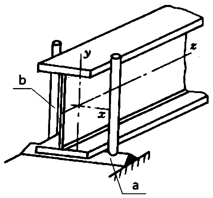
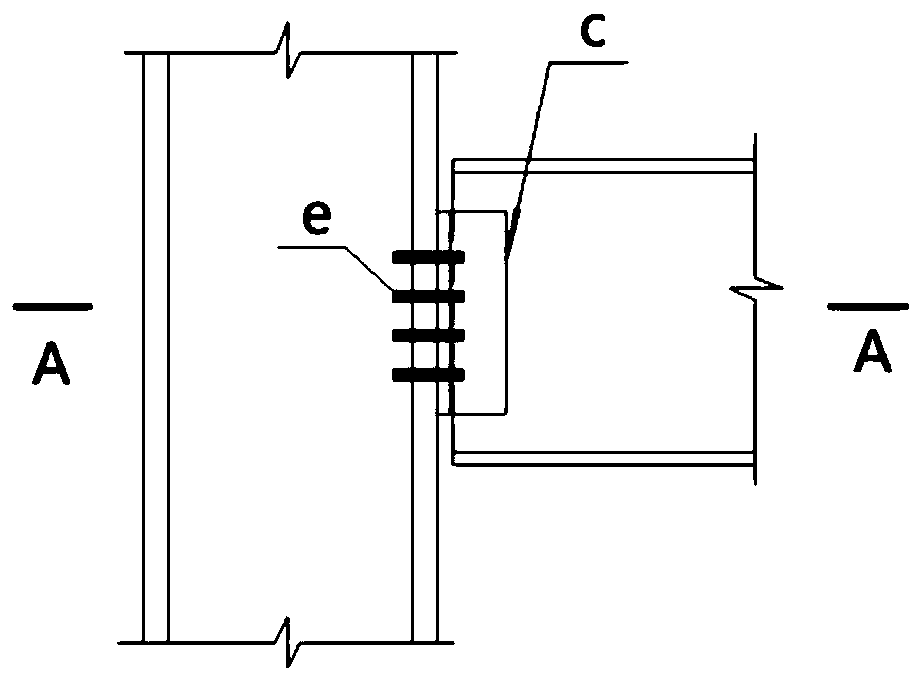
[0060] The embodiment of the present invention provides a beam-column hinge connection node, the schematic diagram of its structure disassembly is as follows Figure 4 As shown, the schematic diagram of its structure after installation is shown in Figure 5 As shown, it includes: a fixing assembly 1 , a fixing bracket 2 and a first elastic buffer piece 3 .

[0061] Wherein, the fixing assembly 1 includes a first plate body 101, a second plate body 102 and a third plate body 103, the side end surface of the first plate body 101 is connected with the steel column 4, and the second plate body 102 and the third plate body 103 are connected to the inner side of the first plate body 101;

[0062] The first elastic buffer sheet 3 is clamped between the inne...


PUM


Abstract

The invention discloses a beam-column hinged connection joint and belongs to the field of steel structures. The beam-column hinged connection joint utilizes a fixing assembly, a fixing bracket and a first elastic buffering piece and is fixed to a steel column through the fixing assembly and a stiffening plate. A second plate body and a third plate body are arranged on the inner side plate face ofa first plate body, a first flange of a steel beam is clamped through the fixing assembly and the stiffening plate, so that the first flange of the steel beam is fixed between the second plate body and the third plate body, and the steel beam cannot rotate around the direction, parallel to the first flange, a second flange and a web, serving as the axis. The second flange of the steel beam is connected to a top plate, thus when the steel beam is under outer force, the fixing bracket can serve as a supporting point, by squeezing the first elastic buffering piece, the steel beam rotates around the direction, perpendicular to the first flange, the second flange and the web, serving as the axis, the structural safety is improved, and the structural potential safety hazard is eliminated.

Description

technical field [0001] The invention relates to the field of steel structures, in particular to a beam-column hinge connection node. Background technique [0002] Simply supported beam is a beam structure commonly used in engineering, and the steel beam is connected to the steel column through hinged nodes at both ends. The schematic diagram of the hinged joint under ideal conditions is as follows: figure 1 As shown, by setting a horizontal support seat a and two rods b on the surface of the steel column, one end of the steel beam can be erected on the support seat a and fixed by the rod body b. The steel beam can realize: (1) winding The axis is free to rotate along the direction parallel to the two flanges and perpendicular to the web, such as figure 1 (2) It cannot rotate freely around the axis parallel to the direction of the two flanges and the web, such as figure 1 in the z-axis. [0003] Schematic diagram of the joint joints commonly used in actual engineering, su...

Claims


Application Information

Patent Timeline
Patent Type & Authority Patents(China)
IPC IPC(8): E04B1/24E04B1/58
Inventor 黄友强陈世玺谢丽萍金靖王长山张爱中高昊嘉罗春霞冯云霞李鸿维
Owner STATE NUCLEAR ELECTRIC POWER PLANNING DESIGN & RES INST CO LTD
Why Eureka
Try Eureka