Viscous damping wall

A technology of viscous damping and wall panels, which is applied in the field of viscous damping walls, can solve problems such as unstable damping coefficient, troublesome filling process, and out-of-surface deformation of interpolated panels, so as to improve construction efficiency, energy dissipation efficiency, and increase The effect of intensity

Active Publication Date: 2018-07-24
CHINA RAILWAY BRIDGE SCI RES INST LTD +2
View PDF9 Cites 1 Cited by
  • Summary
  • Abstract
  • Description
  • Claims
  • Application Information

AI Technical Summary

Problems solved by technology

However, this patent has the following two disadvantages: ① The structure of the damping wall is complicated, and the bolt holes are opened on the inner plate, and the viscous material can only be injected from the bottom after the wall is assembled. The viscosity of the material is high, and the whole filling process is still very troublesome
②The inner insert plate is not strengthened laterally, so when the damping wall is working, the inner insert plate may have a large out-of-plane deformation, the damping coefficient is unstable and affects the service life of the damping wall
However, there are technical shortcomings in this patent: the distance between the two sides of the folded plate type interposer and the container wall is different, resulting in different viscous shear rates of the damping materials on both sides of the interposer, and the damping energy consumption efficiency of the viscous material is not high.

Method used


Image

  • Viscous damping wall
  • Viscous damping wall
  • Viscous damping wall

Examples


Embodiment 1

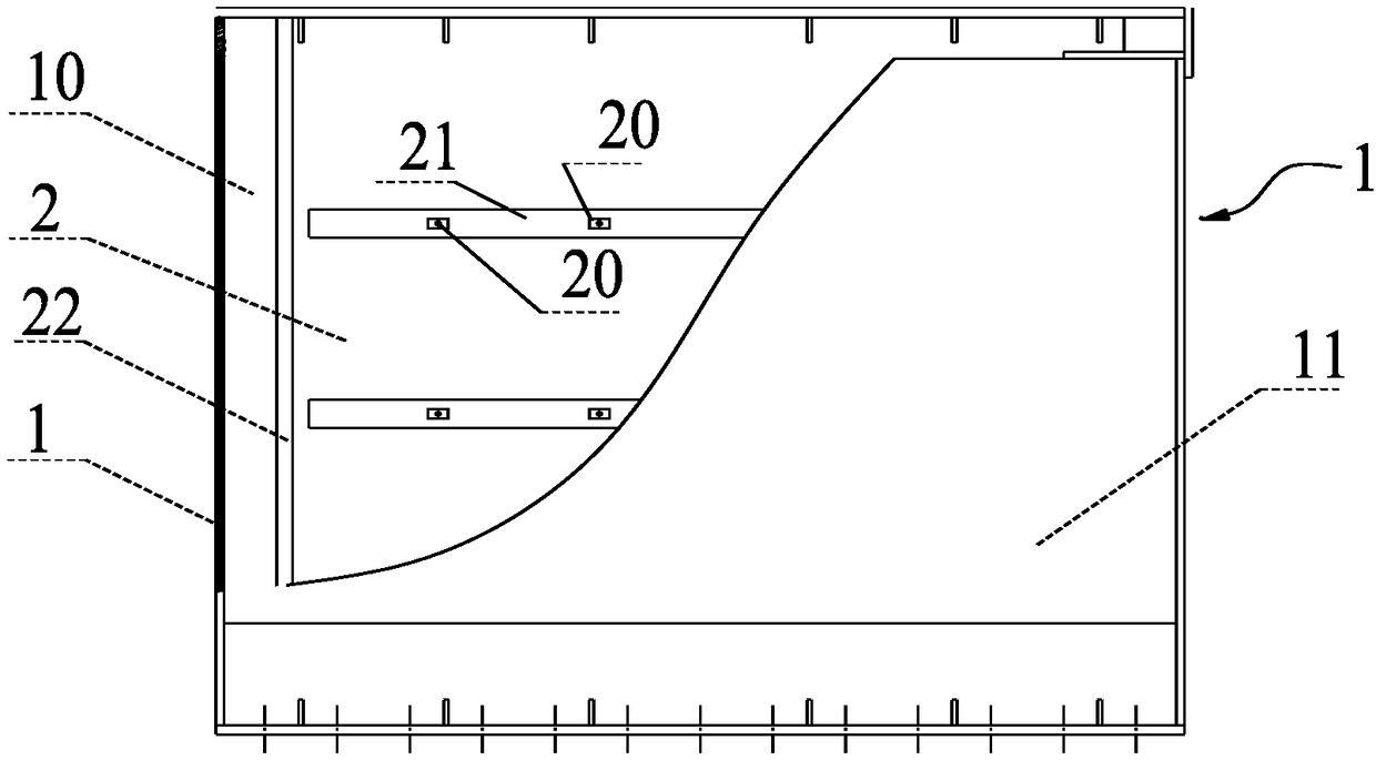
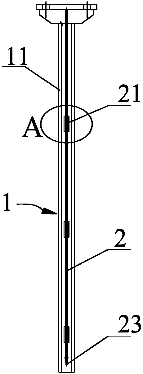
[0040] see figure 1 and figure 2 As shown, the embodiment of the present invention provides a viscous damping wall, which includes a lower container 1 , an inner plate 2 and a resisting member 20 .

[0041] The lower container 1 includes two parallel wallboards 11 arranged at intervals, and the two wallboards 11 are connected by side walls on both sides, and a storage cavity 10 is formed between the two wallboards 11, and viscous materials are accommodated in the storage cavity 10.

[0042] The inner insert board 2 is arranged in the storage chamber 10, and the inner insert board 2 is parallel to the wallboard 11. When the viscous damping wall is subjected to vibration and the inner insert board 2 moves relative to the storage chamber 10 and the wallboard 11, due to the inner The inserting board 2 is parallel to the wallboard 11, and the inner inserting board 2 can move parallel to the wallboard 11, which ensures that the viscous material can better absorb energy. In order ...

Embodiment 2

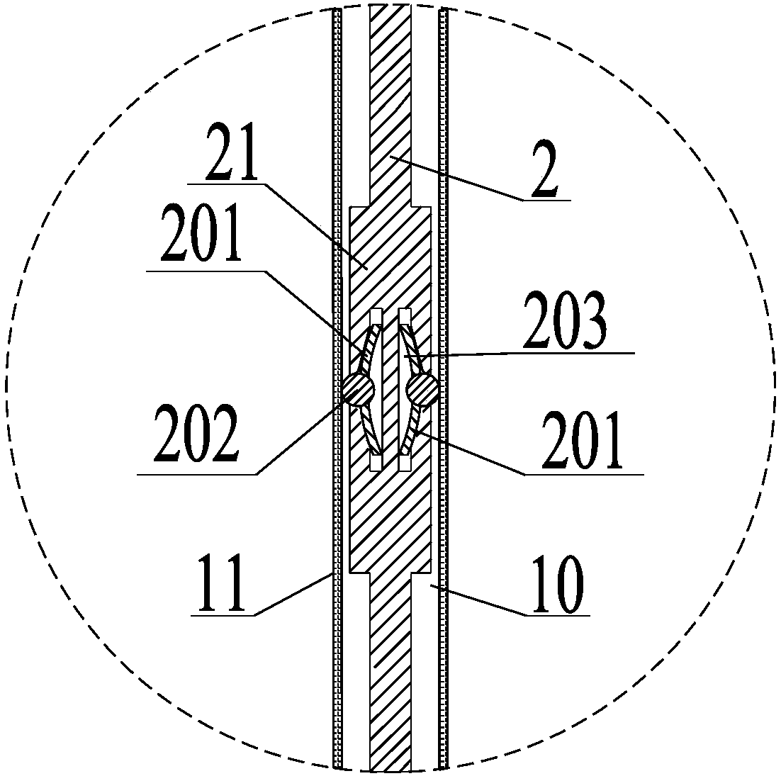
[0047] see image 3 and Figure 4As shown, the difference between the viscous damping wall provided by the present invention and the first embodiment is that the resisting member 20 elastically resists on the wall panel 11 . When the resisting member 20 only slides and resists but does not have elasticity, when the damping wall is subjected to vibrations and other effects, the inner insert board 2 will move relative to the receiving cavity 10, and the inner insert plate 2 will be easily stuck in the receiving cavity 10. After the inner board 2 is stuck in the receiving chamber 10, the inner board 2 cannot move relative to the receiving chamber 10, cannot be hindered by the viscous material, and finally cannot normally dissipate energy. The elastic member is provided so that the resisting structure can elastically resist against the inner wall of the receiving chamber 10. During the vibration process, when it encounters a position that is easy to be stuck, the resisting member...

Embodiment 3

[0054] see Figure 6 As shown, the present invention provides a viscous damping wall, which differs from Embodiment 2 in that: the lower container 1 is provided with two parallel interposers 2, and there is a gap between the two interposers 2. A wall panel 11 is provided. When the construction party needs a larger damping force, three wall bodies 11 connected by side walls can be provided, and viscous material can be filled between two adjacent wall bodies 11 and interposers 2 can be arranged at intervals. When this embodiment is subjected to vibration, the two inner panels 2 in the wall 11 will move in the viscous material at the same time. Compared with one inner panel 2, it provides a greater damping force, and the energy dissipation will be more efficient. And due to faster performance, the wall is more stable.

[0055] Further, more than four walls 11 can be arranged in the viscous damping wall, and viscous material and interposer 2 can be filled between the walls 11 . ...


PUM


Abstract

The invention discloses a viscous damping wall, and relates to the technical field of building structure vibration reduction and earthquake proofing. The viscous damping wall comprises a lower container, an inner inserting plate and butting components, wherein the lower container comprises two wall plates in parallel arrangement at intervals; the two wall plates are connected at two sides throughside walls; an accommodating cavity is formed between the two wall plates; a viscous material is accommodated in the accommodating cavity. An inner inserting plate is arranged in the accommodating cavity and is parallel to the wall plates; the inner inserting plate and the two wall plates are in arrangement at equal intervals; stiffening ribs are arranged on the inner inserting plate. Meanwhile, the butting components are arranged on two side surfaces of the inner inserting plate; the butting components are glidingly abutted against the wall plates. The viscous damping wall has the advantagesthat the surface outer rigidity of the inner inserting plate of the damping wall can be improved; the energy dissipation efficiency of the viscous material is improved; the manufacturing and installing work is simplified.

Description

technical field [0001] The invention relates to the technical field of vibration reduction and anti-seismic technology of building structures, in particular to a viscous damping wall. Background technique [0002] With the development of my country's economy and society, a large number of high-rise building structures have been built in major cities in my country to meet the needs of commercial and residential buildings. In order to ensure the safety of the structure, on the one hand, the code restricts the rigidity of the structure. For example, the "Technical Regulations for Concrete Structures of High-Rise Buildings" stipulates the limit value of interstory displacement of different types of high-rise building structures. On the other hand, some non-load-bearing components of structures (such as supports, shear walls, connectors, etc.) , node) with a damping device installed. When an earthquake occurs, as the lateral deformation of the structure increases, the energy-di...

Claims


Application Information

Patent Timeline
Patent Type & Authority Applications(China)
IPC IPC(8): E04H9/02E04B1/98
CPCE04B1/98E04H9/021E04H9/023
Inventor 汪正兴王波柴小鹏韩伟王梓宇荆国强吴肖波刘鹏飞马长飞王翔
Owner CHINA RAILWAY BRIDGE SCI RES INST LTD
Why Eureka
Try Eureka