Hydraulic synchronous distribution motor with unloading function

A hydraulic synchronous, shunt motor technology, applied in the direction of servo motor components, fluid pressure actuators, servo meter circuits, etc., can solve the problems of energy consumption, uneconomical, time-consuming, etc., to reduce heat, improve efficiency, save energy effect

Pending Publication Date: 2018-07-24
XUZHOU JOY TECH
View PDF0 Cites 4 Cited by
  • Summary
  • Abstract
  • Description
  • Claims
  • Application Information

AI Technical Summary

Problems solved by technology

At present, the function of existing synchronous motors with valves is limited to providing overload and oil supplement functions. When some branches in the synchronous circuit complete their working strokes in advance, the period of waiting for other branches to complete their respective working strokes is also called During the elimination of synchronization error, the system can only consume the energy of the part of the branch that has completed the working stroke in the form of overflow
And because the overflow works as an overload protection, the pressure is usually 1-2MPa higher than the maximum load pressure, so it consumes energy at the most difficult time, which is not only time-consuming, but also uneconomical. Severe heat generation, which may cause increased internal leakage, vibration, howling and other problems; the function of the supercharger is not well utilized

Method used


Image

  • Hydraulic synchronous distribution motor with unloading function
  • Hydraulic synchronous distribution motor with unloading function
  • Hydraulic synchronous distribution motor with unloading function

Examples


Embodiment Construction

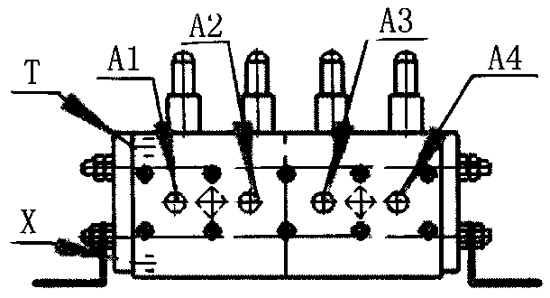
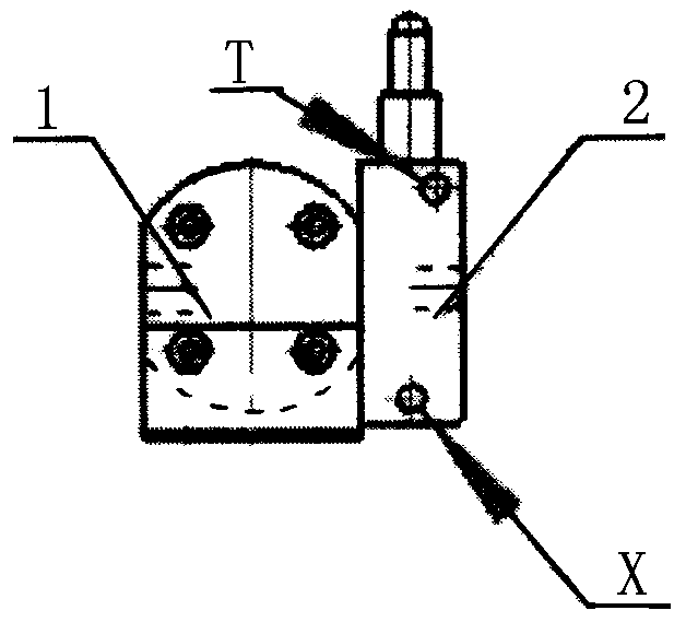
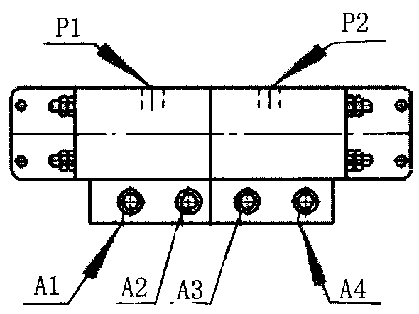
[0017] figure 1 , figure 2 , image 3 and Figure 4 As shown, the present invention takes a four-way gear type hydraulic synchronous motor as an example, including a hydraulic synchronous motor body 1 and an externally controlled valve group 2, the externally controlled valve group is installed on the output end of the hydraulic synchronous motor body, and the externally controlled valve group There are external control ports X and T on the group. The hydraulic synchronous motor body is composed of four hydraulic motors that are independent on the oil circuit and rigidly connected together on the transmission. The input ends of the four hydraulic motors 6 are connected together, while the output ends are independent. On the hydraulic synchronous motor body 1, there are two connected oil inlets P1, P2 and four independent oil outlets A1, A2, A3 , A4, oil inlets and oil outlets are respectively provided on the four hydraulic motors.

[0018] The externally controlled valve...


PUM


Abstract

The invention discloses a hydraulic synchronous distribution motor with the unloading function. The hydraulic synchronous distribution motor with the unloading function comprises a hydraulic synchronous motor body and an external control type group valve. The hydraulic synchronous distribution motor with the unloading function is characterized in that the hydraulic synchronous motor body is composed of a plurality of hydraulic motors which are independently arranged on an oil circuit and are rigidly connected together in transmission, the external control type group valve is installed at the output end of the hydraulic synchronous motor body, a plurality of external control oil ports are arranged on the external control type group valve, the input ends of the hydraulic motors communicate with one another, the output ends of the hydraulic motors are independent from one another, a plurality of communicated oil inlets and a plurality of independent oil outlets are arranged on the hydraulic synchronous motor body, and each hydraulic motor is provided with an oil inlet and an oil outlet. The hydraulic synchronous distribution motor with the unloading function has the advantages that according to the motor, a common one-way valve is replaced by the external control type group valve, the pilot operated check valve can be opened reversely by applying external pressure, and therefore the flow gathering function is achieved, energy is saved furthermore, and therefore the operation efficiency of the hydraulic system is improved.

Description

technical field [0001] The invention relates to a hydraulic cylinder system or any system connected with an external accumulator, in particular to a hydraulic synchronous shunt motor with an unloading function. Background technique [0002] At present, in the hydraulic system, the most cost-effective way to achieve synchronous motion is to use a hydraulic synchronous shunt motor. Hydraulic synchronous shunt motors can generally be referred to as synchronous motors or shunt motors for short. They are mostly used to distribute oil to multiple branches in proportion (according to the direction of the oil circuit, they can be divided into split flow and flow collection), and are commonly used for equal flow oil supply. Mainly used to solve oil cylinder synchronization, travel motor synchronization, etc. In addition, the synchronous motor can also be used as a supercharger in addition to being used for synchronous use. The so-called "supercharger" refers to directing some chamb...

Claims


Application Information

Patent Timeline
Patent Type & Authority Applications(China)
IPC IPC(8): F15B15/08F15B13/06
CPCF15B15/08F15B13/06F15B2211/7058F15B2211/71F15B2211/72
Inventor 孟建邢安任亮匡增河
Owner XUZHOU JOY TECH
Why Eureka
Try Eureka