
Public road anti-vehicle retrograde device and its application in municipal roads

A technology for vehicles and roads, which is applied in the field of devices that can effectively prevent vehicles from going backwards on public roads. It can solve the problems of casualties, vehicle direction loss of control, etc., and achieve good adaptability, good safety, and small size.

Active Publication Date: 2020-07-03
胡增团
View PDF9 Cites 0 Cited by
  • Summary
  • Abstract
  • Description
  • Claims
  • Application Information

AI Technical Summary

Problems solved by technology

[0006] In addition, the above-mentioned invention documents all puncture the driving front wheels. When the front wheels are punctured, the direction of the car will be out of control, causing heavy casualties. Ideally, the rear wheels of the car should be punctured. It shows that for a car running at high speed, the hazard of a rear tire blowout is far less than that of a front tire

Method used


Image

  • Public road anti-vehicle retrograde device and its application in municipal roads
  • Public road anti-vehicle retrograde device and its application in municipal roads
  • Public road anti-vehicle retrograde device and its application in municipal roads

Examples


Embodiment 1

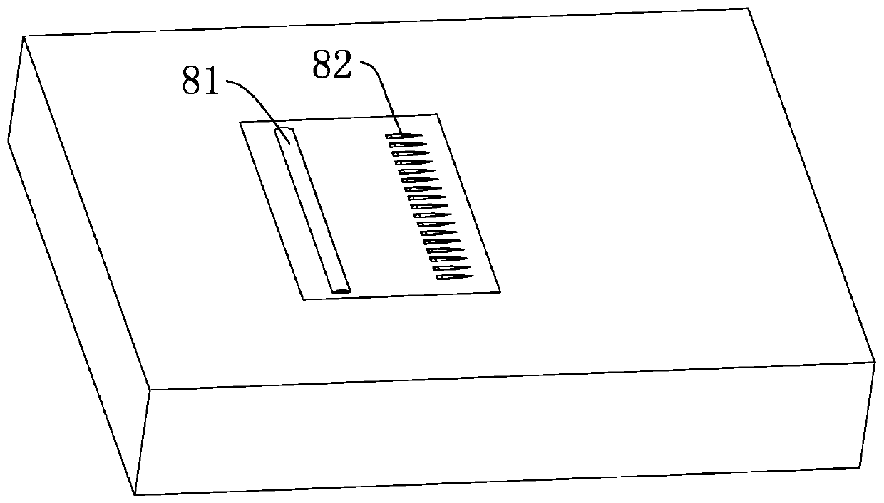
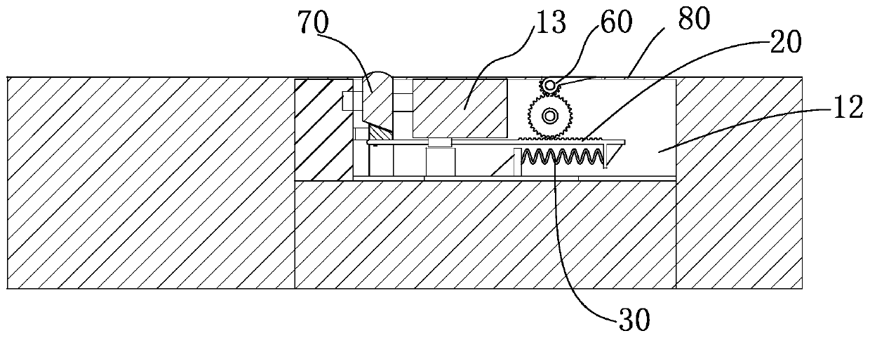
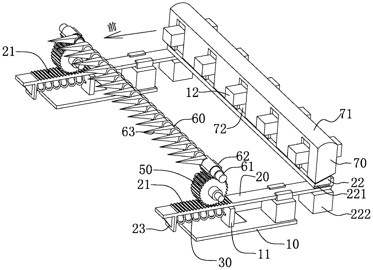
[0051] Example one, reference Figure 1 to Figure 5 , The device includes a base 10, a linear guide 20, a compression spring 30, a leaf spring 40, a large gear 50, a barbed roller 60, a wedge block 22, a lower pressing block 70, a cover plate 80 and related shaft sleeves, bearings, etc., It will be described in detail below in conjunction with the installation process.

[0052] The base 10 is fixed in the trench 12 of the road to install other components, for example, welded by section steel and steel plate. The style is designed according to the structure of the trench and the needs of the parts to be installed. The functional structure on the base 10 It will be explained in the following discussion.

[0053] A linear slide groove is installed on the left and right sides of the base 10, and a linear guide 20 is installed in the slide groove. The linear guide 20 slides in the front and rear direction in the slide groove. The upper surface of the front half of the linear guide is m...

Embodiment 2

[0063] The difference from the first embodiment lies in the arrangement relationship between the barb roller and the large gear. In the first embodiment, the axis of the barb roller and the large gear are arranged up and down. In the second embodiment, refer to Figure 8 , The large gear 50 is axially at the back and bottom of the barb roller 60, that is, it forms a collinear relationship with the barb portion after it bounces, and supports the barb roller. The force performance of the barb roller is better than that of the first embodiment Layout.

[0064] This device is usually installed in some special occasions, such as one-way lanes, non-motorized lanes, etc.


PUM


Abstract

The invention discloses a device for preventing vehicles from converse running on public roads and an application of the device to municipal roads, and is used for providing a municipal facility witha new structure. The device comprises a cover plate, linear guideways, a large gear and a barbed roller, wherein two parallelly-arranged bases are fixed in ground grooves, and the bases are the linearguideways; the linear guideways are connected with the barbed roller by a rack and pinion structure; resilient elements for resetting are arranged between the linear guideways and the bases or between the linear guideways and the ground grooves; when the resilient element are in a relaxed state, arc tops protrude out of first windows, and stabs are hidden in the ground grooves; after a pressing block is pressed down, the large gear and the barbed roller are driven to rotate, so that the stabs protrude out to be above the cover plate. According to the device, by setting the elastic coefficients of compression springs and leaf springs, the stabs protrude out only when a vehicle exceeding the designed weight passes the device, to force the vehicle to stop, the stabs do not protrude out whena non-motor vehicle passes, and thus the security is high.

Description

Technical field [0001] The invention relates to the technical field of public safety facilities, in particular to a device that effectively prevents vehicles from going backwards on public roads. Background technique [0002] With the popularity of family cars, the traffic flow in public transportation has increased sharply, and there is an even more need for orderly, safe, and standardized driving of vehicles. However, whether it is on ordinary municipal roads or highways, many drivers often drive in the opposite direction on one-way or traffic lanes for their own convenience and speed. This will cause traffic disorder, and there may be traffic accidents and harm Public safety. [0003] In view of the above content, some inventors have proposed measures to prevent retrograde equipment to restrict the driving behavior of vehicles. For example, the Chinese patent: CN 204530552 U. The proposal includes: an anti-reversing block body, one end of which is provided with an assembly hol...

Claims


Application Information

Patent Timeline
Patent Type & Authority Patents(China)
IPC IPC(8): E01F13/10E01F13/12
CPCE01F13/105E01F13/123
Inventor 胡增团冯小宝刘博孔瑞清
Owner 胡增团
Learn More