Eureka AIR delivers breakthrough ideas for toughest innovation challenges, trusted by R&D personnel around the world.

Novel flow valve

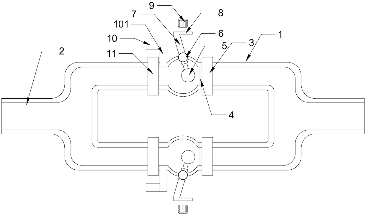
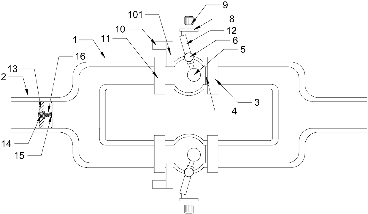
A flow valve and a new type of technology, applied in the field of flow valves, can solve the problems of reduced flow control effect, small flow of flow valve, blockage of impurities, etc., and achieve the effects of simple structure, cleanness and long service life.

Pending Publication Date: 2018-07-24
TIANJIN ZHI YUAN IND & TRADE
View PDF5 Cites 2 Cited by
  • Summary
  • Abstract
  • Description
  • Claims
  • Application Information

AI Technical Summary

Problems solved by technology

[0002] After the flow valve in the prior art is used for a period of time, it will be blocked by impurities, resulting in a small flow rate of the flow valve, and at the same time, the flow control effect will also be reduced

Method used


Image

  • Novel flow valve
  • Novel flow valve

Examples


Embodiment Construction

[0018] It should be noted that, in the case of no conflict, the embodiments of the present invention and the features in the embodiments can be combined with each other.

[0019] In describing the present invention, it should be understood that the terms "center", "longitudinal", "transverse", "upper", "lower", "front", "rear", "left", "right", The orientations or positional relationships indicated by "vertical", "horizontal", "top", "bottom", "inner", "outer", etc. are based on the orientation or positional relationships shown in the drawings, and are only for the convenience of describing the present invention Creation and simplification of description, rather than indicating or implying that the device or element referred to must have a specific orientation, be constructed and operate in a specific orientation, and therefore should not be construed as limiting the invention. In addition, the terms "first", "second", etc. are used for descriptive purposes only, and should no...


PUM


Abstract

The invention provides a novel flow valve which is characterized in that flow valve bodies are arranged on branch pipes; filter screens are arranged in the parts, on one sides of water inlets of the flow valve bodies, of the branch pipes; stain removal balls are arranged at the parts, on one water inlet sides of the filter screens, in the branch pipes; the stain removal balls are arranged at one ends of connecting rods; the stain removal balls can be in contact with the filter screens; cut-off valves are arranged on one sides, far away from the filter screens, of the stain removal balls; the connecting rods are connected with the pipe walls of the branch pipes through universal couplings; the other ends of the connecting rods protrude out of the branch pipes and are fixedly connected withthe parts, close to the edges, of the end faces of rotary discs; the rotary discs are fixedly connected with output shafts of speed reducers; and the rotary discs and the output shafts of the speed reducers are coaxial. The novel flow valve is simple in structure, impurities like scale deposits in a pipeline can be discharged out of the pipeline regularly, the cleaning effect is good, and the service life is long.

Description

technical field [0001] The invention belongs to the technical field of flow valves, and in particular relates to a novel flow valve. Background technique [0002] After the flow valve in the prior art is used for a period of time, it will be blocked by impurities, resulting in a small flow rate of the flow valve, and at the same time, the flow control effect will also be reduced. Contents of the invention [0003] In view of this, the present invention aims to propose a novel flow valve to solve the above technical problems. [0004] In order to achieve the above object, the technical solution created by the present invention is achieved in this way: [0005] A new type of flow valve, the flow valve is set on the branch pipeline, a filter screen is arranged in the branch pipeline on the side of the water inlet of the flow valve, and a decontamination ball is arranged in the branch pipeline on the water inlet side of the filter screen, and the decontamination ball is set ...

Claims


Application Information

Patent Timeline
IPC IPC(8): F16K51/00F16L55/24B08B9/027B01D35/04
CPCB01D35/04F16K51/00F16L55/24B08B9/027
Inventor 孟繁君庞东生
Owner TIANJIN ZHI YUAN IND & TRADE
Why Eureka
Eureka Blog
Learn More