Shearing box as well as stress testing method and device
A technology of shear box and box body, which is applied in the direction of applying stable shear force to test the strength of materials, measuring devices, instruments, etc., which can solve large measurement errors and increase the friction between the upper shear box and the slide rail , troublesome installation and disassembly of samples, etc., to achieve accurate measurement, improve efficiency and measurement accuracy
- Summary
- Abstract
- Description
- Claims
- Application Information
AI Technical Summary
Problems solved by technology
Method used
Image

Examples
no. 1 example
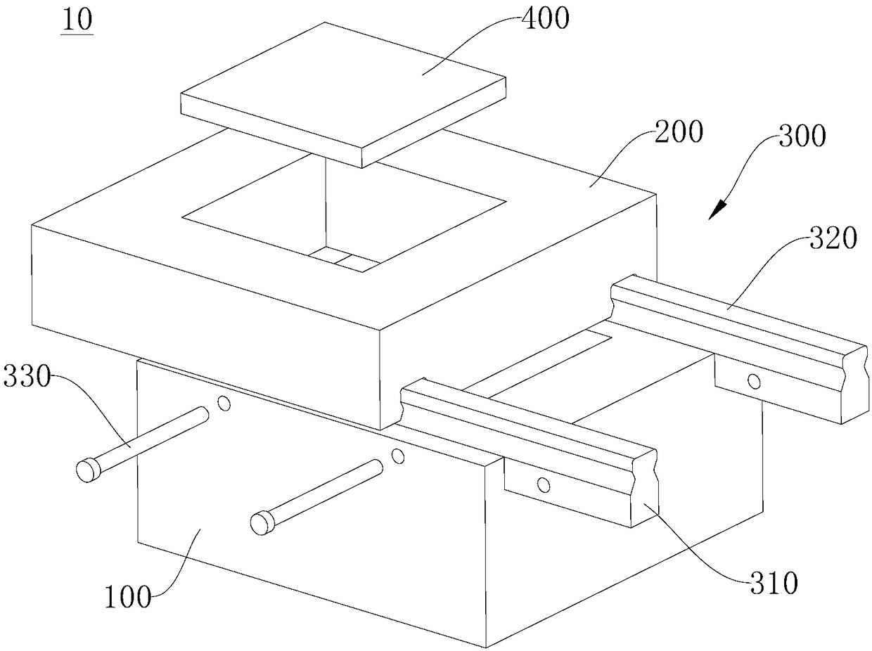
[0040] Please refer to Figure 1 to Figure 4 , this embodiment provides a shear box 10, which has the characteristics of simple structure, convenient use, and small measurement error, and can facilitate the installation and disassembly of samples, which is conducive to improving the efficiency and measurement accuracy of the test.
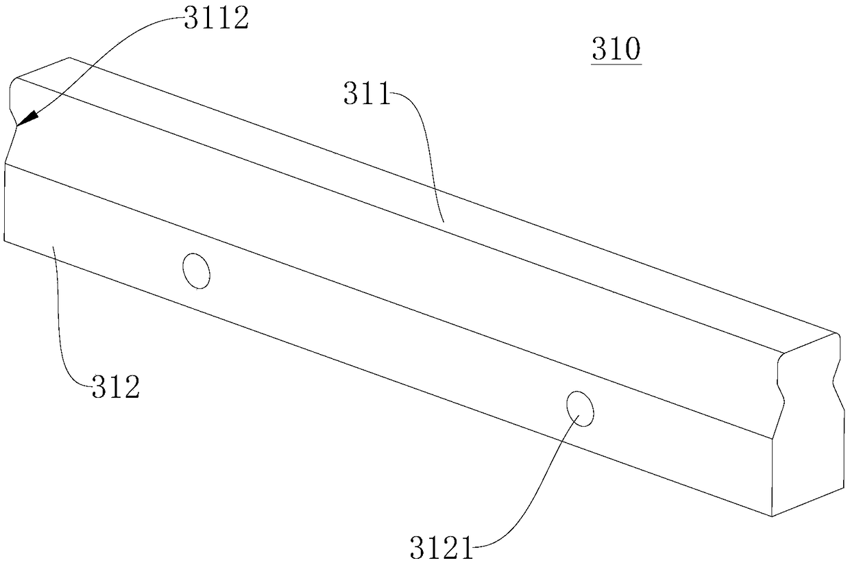
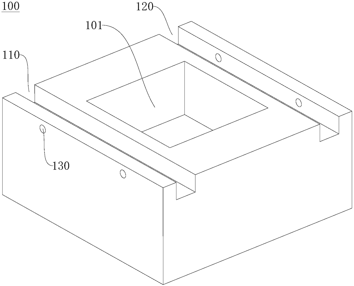
[0041] The shear box 10 provided in this embodiment includes a first box body 100 , a second box body 200 , a slide rail assembly 300 and a gasket 400 . The first box body 100 is provided with a first chamber 101, a first chute 110 and a second chute 120, the first chamber 101 is located between the first chute 110 and the second chute 120, and the first chute 110 and the second chute 120 are arranged parallel to each other. The second box body 200 is provided with a second chamber 202, a first installation groove 210 and a second installation groove 220, the second chamber 202 is arranged through and communicated with the first chamber 101, and t...
no. 2 example
[0055] Please refer to Figure 1 to Figure 4 , this embodiment provides a stress test method using the shear cell 10 provided in the first embodiment. The shear box 10 includes a first box body 100 , a second box body 200 , a slide rail assembly 300 and a spacer 400 . The first box body 100 is provided with a first chamber 101, a first chute 110 and a second chute 120, the first chamber 101 is located between the first chute 110 and the second chute 120, and the first chute 110 and the second chute 120 are arranged parallel to each other. The second box body 200 is provided with a second chamber 202, a first installation groove 210 and a second installation groove 220, the second chamber 202 is arranged through and communicated with the first chamber 101, and the second chamber 202 is located in the first installation groove 210 and the second installation groove 220, the first installation groove 210 and the second installation groove 220 are arranged parallel to each other...
no. 3 example
[0059] Please refer to Figure 1 to Figure 4, this embodiment provides a stress test device (not shown), including a loading mechanism (not shown) and a shear box 10 . The shear box 10 includes a first box body 100 , a second box body 200 , a slide rail assembly 300 and a spacer 400 . The first box body 100 is provided with a first chamber 101, a first chute 110 and a second chute 120, the first chamber 101 is located between the first chute 110 and the second chute 120, and the first chute 110 and the second chute 120 are arranged parallel to each other. The second box body 200 is provided with a second chamber 202, a first installation groove 210 and a second installation groove 220, the second chamber 202 is arranged through and communicated with the first chamber 101, and the second chamber 202 is located in the first installation groove 210 and the second installation groove 220, the first installation groove 210 and the second installation groove 220 are arranged paral...
PUM
 Abstract
Description
Claims
Application Information
 - Generate Ideas
- Intellectual Property
- Life Sciences
- Materials
- Tech Scout
- Unparalleled Data Quality
- Higher Quality Content
- 60% Fewer Hallucinations
Browse by: Latest US Patents, China's latest patents, Technical Efficacy Thesaurus, Application Domain, Technology Topic, Popular Technical Reports.
© 2025 PatSnap. All rights reserved.Legal|Privacy policy|Modern Slavery Act Transparency Statement|Sitemap|About US| Contact US: help@patsnap.com