Comprehensive vending machine

A vending machine and storage technology, which is applied to instruments, coin-operated equipment for distributing discrete items, coin-operated equipment for distributing discrete items, etc., can solve the problem of low space utilization, large thrust, and inability to achieve volume and other problems, to achieve the effect of simple structure, improved fluidity, and accurate control

Active Publication Date: 2018-07-24
惠州市优侎实业有限公司
View PDF11 Cites 1 Cited by
  • Summary
  • Abstract
  • Description
  • Claims
  • Application Information

AI Technical Summary

Problems solved by technology

[0002] With the development of technology, vending machines are becoming more and more mature. After the goods are stored, the output of the goods can be accurately controlled. However, the control of canned or bottled beverage goods is controlled by using double baffles or push-outs. Dual card Board control is to arrange the goods in the inclined storage tank, by controlling one baffle to block the last goods, another baffle to block the penultimate goods, and then control the last baffle to shrink, the last One cargo slides down, and then the baffle is lifted, and the other baffle is lowered to let the cargo in front fall down. Although this kind of control can accurately control the falling of a single cargo, the control method is complicated, there are many control devices, and the cost is high; The push-out type is to arrange the goods on a plane. Since the storage and placement of the goods need to be considered in this arrangement, the space required for placement is required. The space utilization rate of the overall structure is low, and it is supplementary. The goods need to be arranged one by one, and the efficiency of replenishment is also low. The device is controlled by means of ejection. This method directly pushes the last goods to push out the goods in front. The thrust is relatively large, and the goods will be broken. The phenomenon of overturning the jammed goods, after the goods are overturned, the output of the goods cannot be controlled normally. In addition, when the control device fails, it needs to be disassembled and taken out for maintenance during maintenance, which is inconvenient for maintenance; traditional vending machines sell a single category, There are few items, and the automatic sale of large and heavy goods cannot be realized

Method used


Image

  • Comprehensive vending machine
  • Comprehensive vending machine
  • Comprehensive vending machine

Examples


Embodiment 1

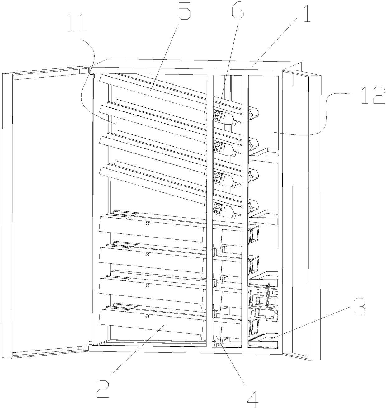
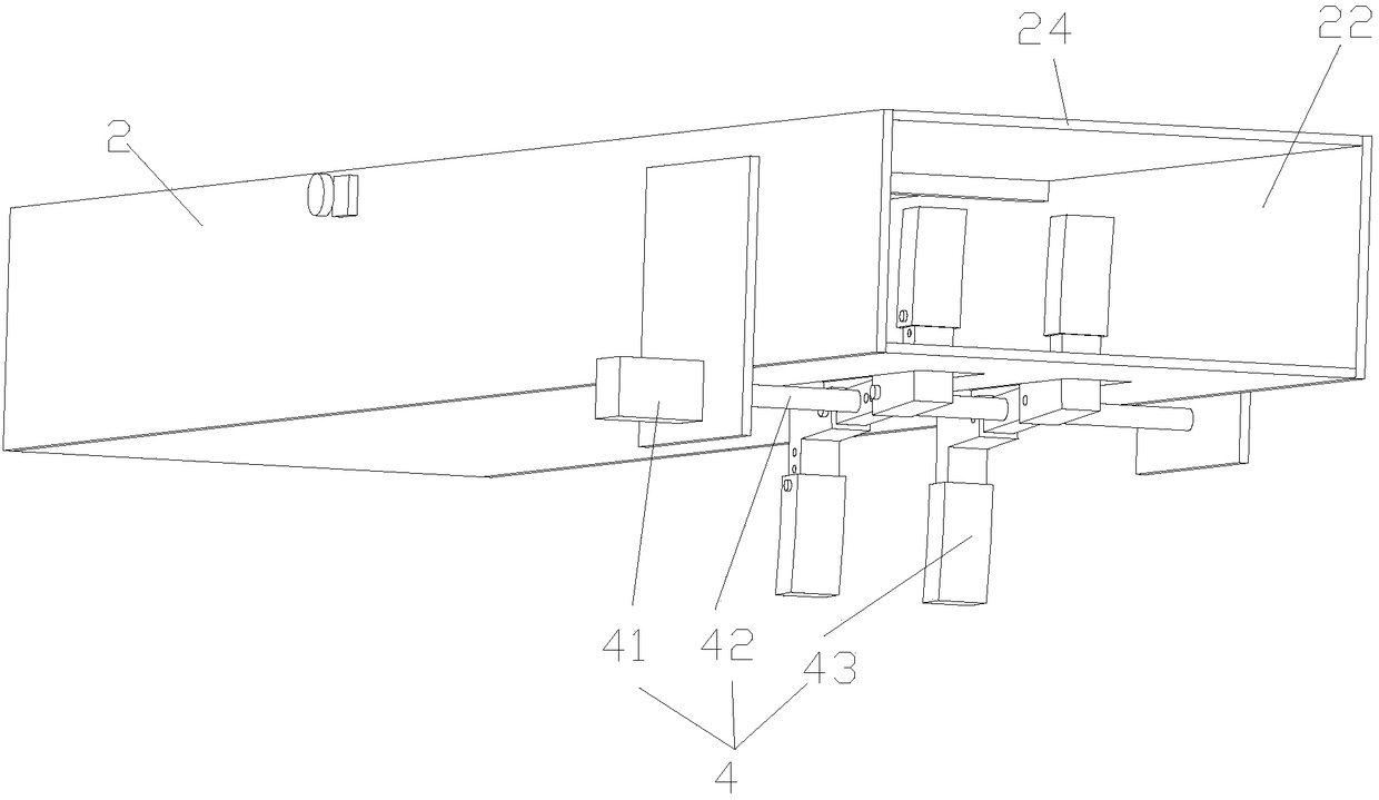
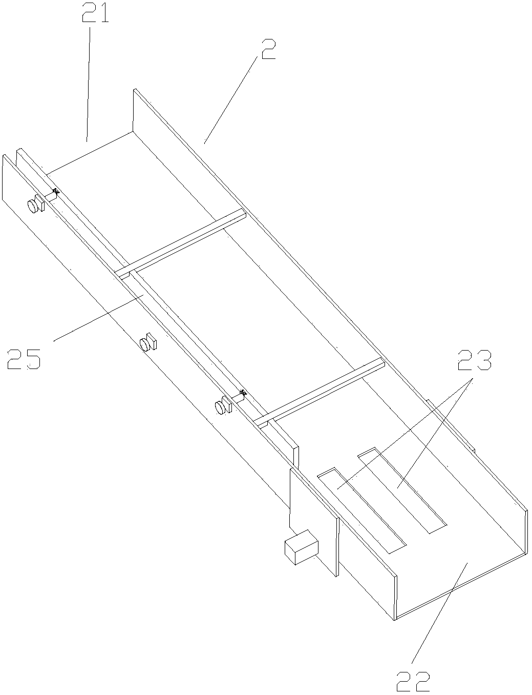
[0039] Embodiment 1: as Figure 1~6 As shown, a comprehensive automatic vending machine includes a box body 1, and the box body 1 is provided with a storage area 11 and a pick-up area 12; the storage area 11 is provided with at least one Inclined first storage tank 2; said picking area 12 is provided with at least one picking tank 3; the left end of said first storage tank 2 has a material inlet 21, and the right end has a material outlet 22; said The first control device 4 that can control the individual output of goods is provided on the first storage tank 2 near the discharge port 22; the first control device 4 includes a first drive device 41, a first rotating shaft 42 and at least one claw 43; the first driving device 41 is drivingly connected to the first rotating shaft 42; the claw 43 is sleeved on the first rotating shaft 42; the claw 43 includes at least two uniformly distributed around the center of the first rotating shaft 42 Clip bar 431 ; the first space-avoiding...

Embodiment 2

[0043] Embodiment 2: In embodiment 1, such as Figure 7 As shown, two limiting parts 431-2 of the clamping strip 431 are provided, the two limiting parts 431-2 and the vertical part 431-1 form a "T" shaped clamping strip, and the two clamping strips form an "H" shape Claws, the goods limiting part 431-2 can be provided with a certain arc, so that the movement is more stable after contact with the goods; after the goods fall, they will enter the vertical part 431-1 of the two clamping bars 431, and pass through the two limiting parts 431-2 is engaged and fixed, and as the first rotating shaft 42 drives the claw 43 to rotate, the claw 43 drives the cargo to be transported, and the next cargo will be blocked due to the turning in of the limiting part 431-2 , the vertical part 431-1 can only be entered and engaged after the limiting part 431-2 is disengaged. At this time, the previous cargo has been transported to the other side by the claw 43 and dropped into the cargo picking gr...

Embodiment 3

[0045] Embodiment 3: as Figure 9 As shown, in the structure of Embodiment 1, three clamping strips 431 are set; the shape of the clamping strips 431 is a vertical strip shape, and the three clamping strips 431 form a "Y"-shaped claw 43, and every two The angle between the two clamping strips 431 is 120°, and the goods are engaged between the two clamping strips 431 to be transported. The first rotating shaft 42 takes out one cargo every 120° rotation, and three cargoes are brought out in one revolution.

[0046] Such as Figure 10 As shown, the clip bar 431 is sleeved with a first connecting piece 432 slidably connected thereto; by adjusting the position of the first connecting piece 432 on the clip bar 431 , it can adapt to goods of different specifications.


PUM


Abstract

The invention provides a comprehensive vending machine which comprises a tank body, wherein a storage zone and a taking zone are arranged inside the tank body; at least one storage trough which is inclined towards a taking direction is formed in the storage zone; a taking trough is formed in the taking zone; a feeding hole is formed in the left end of the first storage trough; a discharge hole isformed in the right end of the first storage trough; a first control device capable of controlling single output of cargos is arranged close to the discharge hole in the first storage trough; the first control device comprises a first driving device, a first rotating shaft and at least one clamping claw; the first driving device is in driving connection with the first rotating shaft; the first rotating shaft is sleeved by the clamping claw; the clamping claw comprises at least two clamping strips which are uniformly distributed around the center of the first rotating shaft; a first avoiding part for avoiding the clamping claw is arranged at the bottom of the first storage trough. The comprehensive vending machine is simple in structure, high in space utilization rate, rapid in cargo replenishing efficiency and simple and convenient to repair.

Description

technical field [0001] The invention relates to the field of automatic vending machines, in particular to a comprehensive automatic vending machine. Background technique [0002] With the development of technology, vending machines are becoming more and more mature. After the goods are stored, the output of the goods can be accurately controlled. However, the control of canned or bottled beverage goods is controlled by using double baffles or push-outs. Dual card Board control is to arrange the goods in the inclined storage tank, by controlling one baffle to block the last goods, another baffle to block the penultimate goods, and then control the last baffle to shrink, the last One cargo slides down, and then the baffle is lifted, and the other baffle is lowered to let the cargo in front fall down. Although this kind of control can accurately control the falling of a single cargo, the control method is complicated, there are many control devices, and the cost is high; The p...

Claims


Application Information

Patent Timeline
Patent Type & Authority Applications(China)
IPC IPC(8): G07F11/16
CPCG07F11/16
Inventor 余灿芳
Owner 惠州市优侎实业有限公司
Why Eureka
Try Eureka