Roller extension socket

A roller, one-way roller technology, applied in contact parts, electrical components, coupling devices, etc., can solve the problems of exposed metal sheets, loose plugs, and difficult to use, and achieve the effect of humanized design, convenient control, and ingenious structure

Pending Publication Date: 2018-07-24
曾成
View PDF0 Cites 1 Cited by
  • Summary
  • Abstract
  • Description
  • Claims
  • Application Information

AI Technical Summary

Problems solved by technology

In the process of using the socket, frequent plugging and unplugging will easily cause the 2-hole plug to loosen, and a part of the metal sheet will be exposed, causing a safety hazard, while the 3-hole plug is difficult to insert and unplug, and it is not easy to use.
And it is easy to ignore whether the power strip itself is powered on if the power strip is placed randomly, so there is still a great safety hazard for people with children or people with limited mobility at home.

Method used


Image

  • Roller extension socket
  • Roller extension socket
  • Roller extension socket

Examples


Embodiment 1

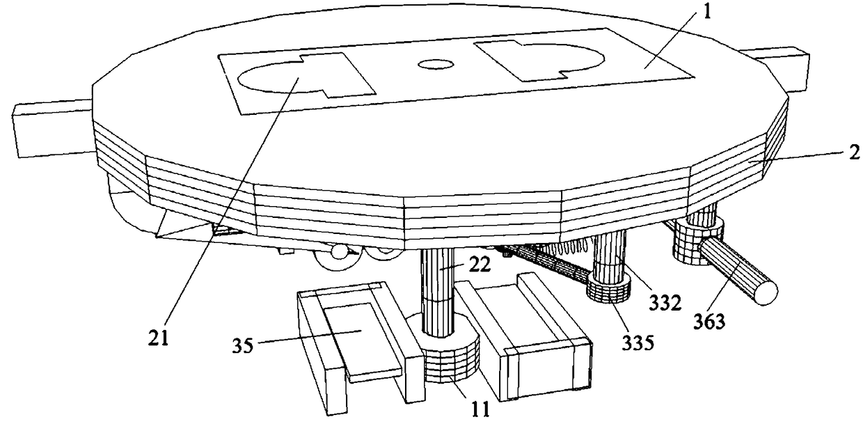
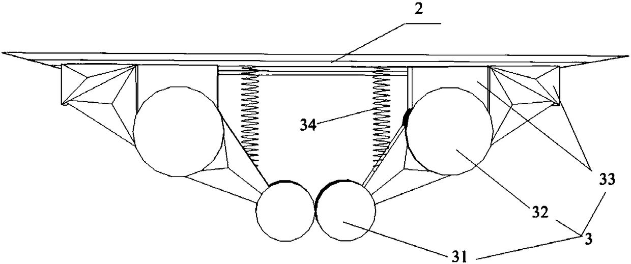
[0032] Such as figure 1 and figure 2 As shown in the roller socket, the roller socket is composed of a body 1, a turntable 2 and a clamping device 3, the turntable 2 rotates on the socket body 1, a socket 21 is provided on the turntable 2, and the clamping device 3 is installed on each socket. At the bottom of the hole 21 , the clamping device 3 is arranged symmetrically with respect to the insertion hole 21 ; the clamping device 3 includes a roller 31 , a moving shaft 32 , a fixing bracket 33 and a first spring 34 . A set of clamping devices 3 is arranged under each socket 21 , and the symmetrical clamping devices with respect to the socket 21 make the force of the entire clamping device uniform and the resistance is minimum, which is convenient for torque transmission.

[0033] Roller 31 is wrapped with rubber, is provided with a center rotating shaft 22 vertically downwards at the center of circle of rotating disc 2, and central rotating shaft 22 can only rotate countercl...

Embodiment 2

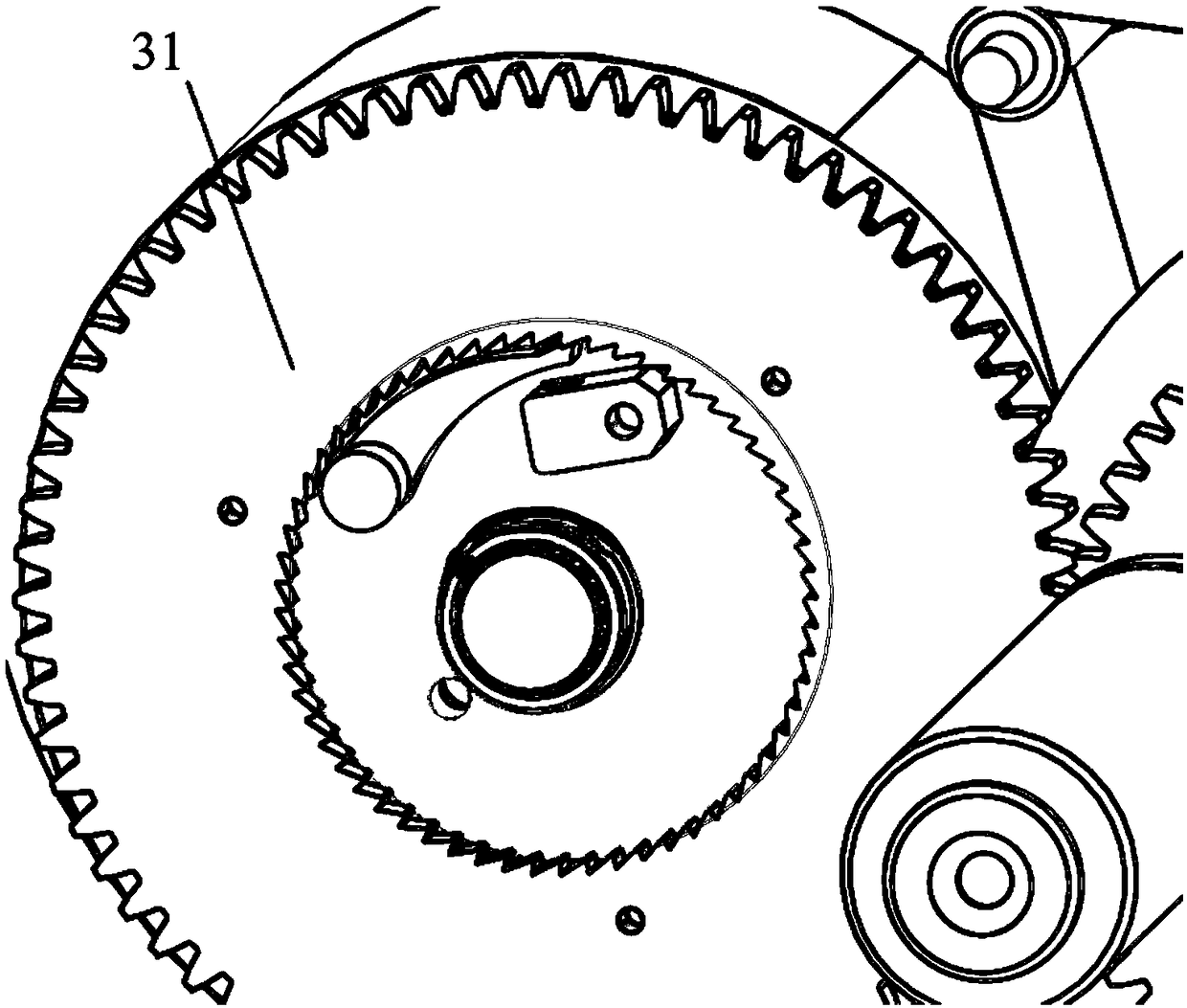
[0036] Since the distance between the metal sheets 100 of the plug is fixed, only 1.15cm, and the installation space required by the fixed bracket in Embodiment 1 is relatively large, in order to better realize the technical effect in Embodiment 1, this In the embodiment, the specific structure of the roller socket is improved to the following structure. The improved internal structure of each jack is asymmetrical, which simplifies the structure on one side, and the unmentioned part of the structure is the same as that of Embodiment 1.

[0037] Such as Figure 3 ~ Figure 5 As shown, the two sides of the clockwork device 11 are provided with card slots, and a metal elastic piece 35 is arranged in the card slot, and the second spring 12 is connected to the lower part of the metal elastic piece 35 . The clockwork device 11 and the second spring 12 are fixed on the main body 1. The second spring 12 provides support for the metal dome 35 when the metal piece 100 is inserted, and a...


PUM


Abstract

The present invention discloses a roller extension socket. The roller extension socket is formed by one or more than one sockets. Each socket comprises one socket body, one rotary table and one clamping device. The rotary tables rotate on the socket bodies, the rotary tables are provided with jacks, and the clamping devices are arranged in the rotary tables. One set of clamping devices is arrangedunder each jack, each clamping device comprises one fixed support, one moving shaft, one moving arm and one roller, one end of each fixed support is fixed at the internal portion of one rotary table,the other end of each fixed support is hinged with one roller through one moving arm, and each two rollers are in contact to each other. metal elastic pieces are arranged under the rollers, metal pieces of plugs are inserted and push out the rollers to insert the metal elastic pieces for electrifying, the metal pieces after insertion cannot be pulled out due to friction, and the contact rollers are separated when the rotary tables are rotated to leave a channel for the metal pieces. The roller extension socket employs a roller structure to allow the plugs to easily insert the extension socketjacks and be firmly fixed on the extension socket, and when the plugs need to be pulled out, the plugs are twisted for 90 degrees in an anticlockwise direction, and the jacks can automatically returnto positions when the plugs are pulled out.

Description

technical field [0001] The invention relates to a roller socket, which belongs to the field of household appliances. Background technique [0002] With the development and popularization of various household appliances, sockets have become one of the indispensable appliances in every family life. The sockets are random and extensible, but the safety of the sockets has been criticized by people. With the increase in the frequency of use of power strips, frequent use of power strips leads to an increasing chance of people getting an electric shock. In the process of using the socket, frequent plugging and unplugging can easily cause the 2-hole plug to loosen, and a part of the metal sheet will be exposed, causing potential safety hazards, while the 3-hole plug is difficult to insert and unplug, and is not easy to use. And it is easy to ignore whether the power strip itself is powered on if the power strip is placed randomly, so there is still a great safety hazard when there ...

Claims


Application Information

Patent Timeline
Patent Type & Authority Applications(China)
IPC IPC(8): H01R13/10H01R13/629H01R13/64H01R13/627
CPCH01R13/10H01R13/627H01R13/629H01R13/64
Inventor 曾成
Owner 曾成
Why Eureka
Try Eureka