
Magnetic type connector composition

A connector combination and magnetic suction technology, which is applied in the direction of connection, parts of the connection device, and a device to prevent wrong connection, etc., can solve the problem that the conductive terminal affects the normal use of electronic equipment, etc.

Active Publication Date: 2018-07-24
FOXCONN (KUNSHAN) COMPUTER CONNECTOR CO LTD +1
View PDF12 Cites 4 Cited by
  • Summary
  • Abstract
  • Description
  • Claims
  • Application Information

AI Technical Summary

Problems solved by technology

In the prior art, the conductive terminal is not surrounded by a metal shell with shielding function, so that the conductive terminal is easily interfered by external signals and affects the normal use of electronic equipment

Method used


Image

  • Magnetic type connector composition
  • Magnetic type connector composition
  • Magnetic type connector composition

Examples


Embodiment Construction

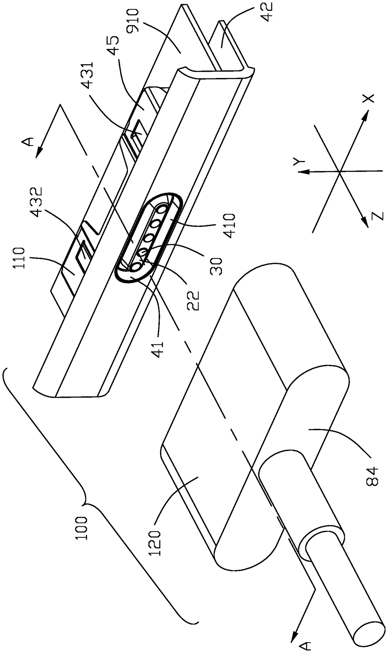
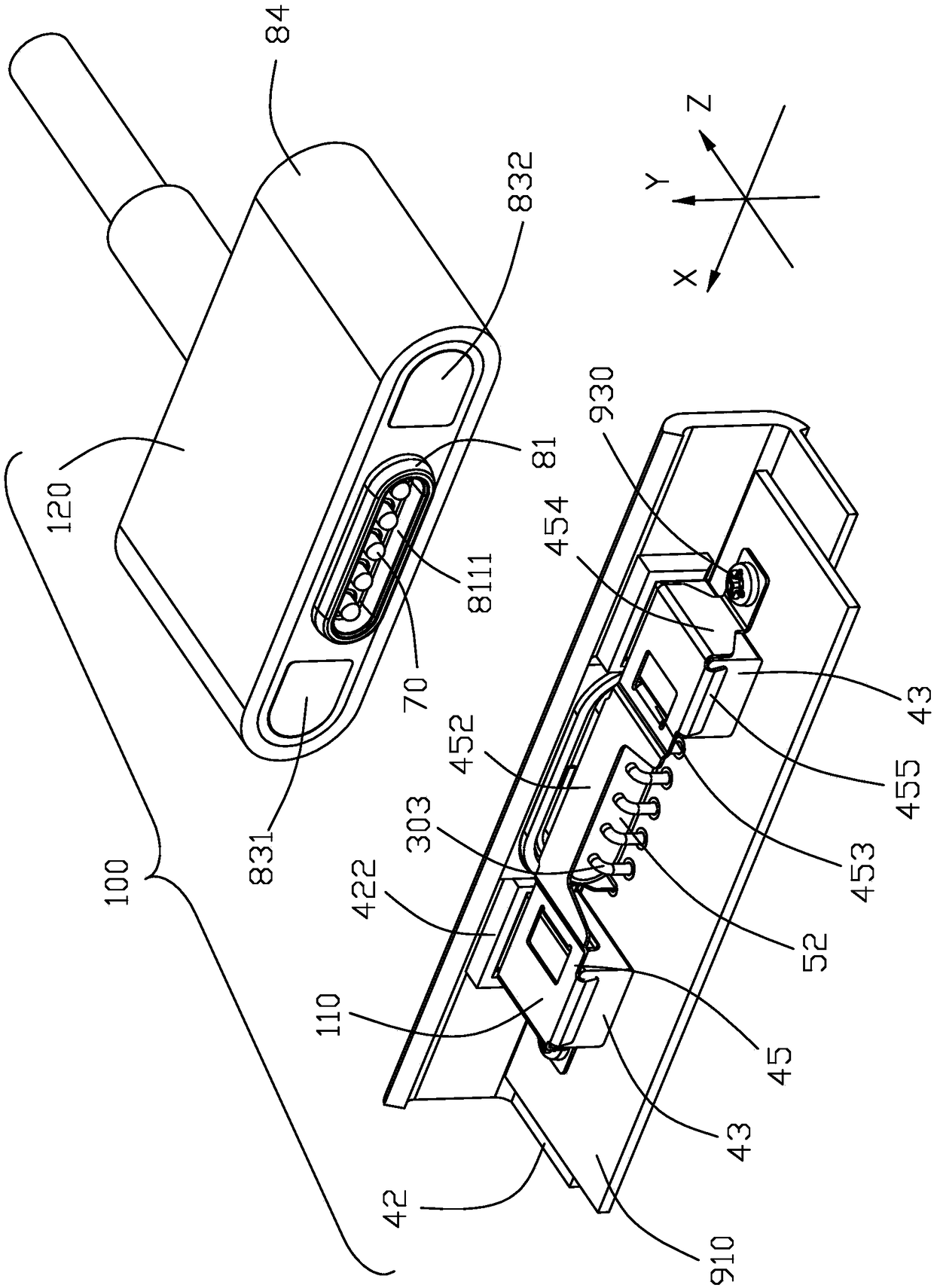
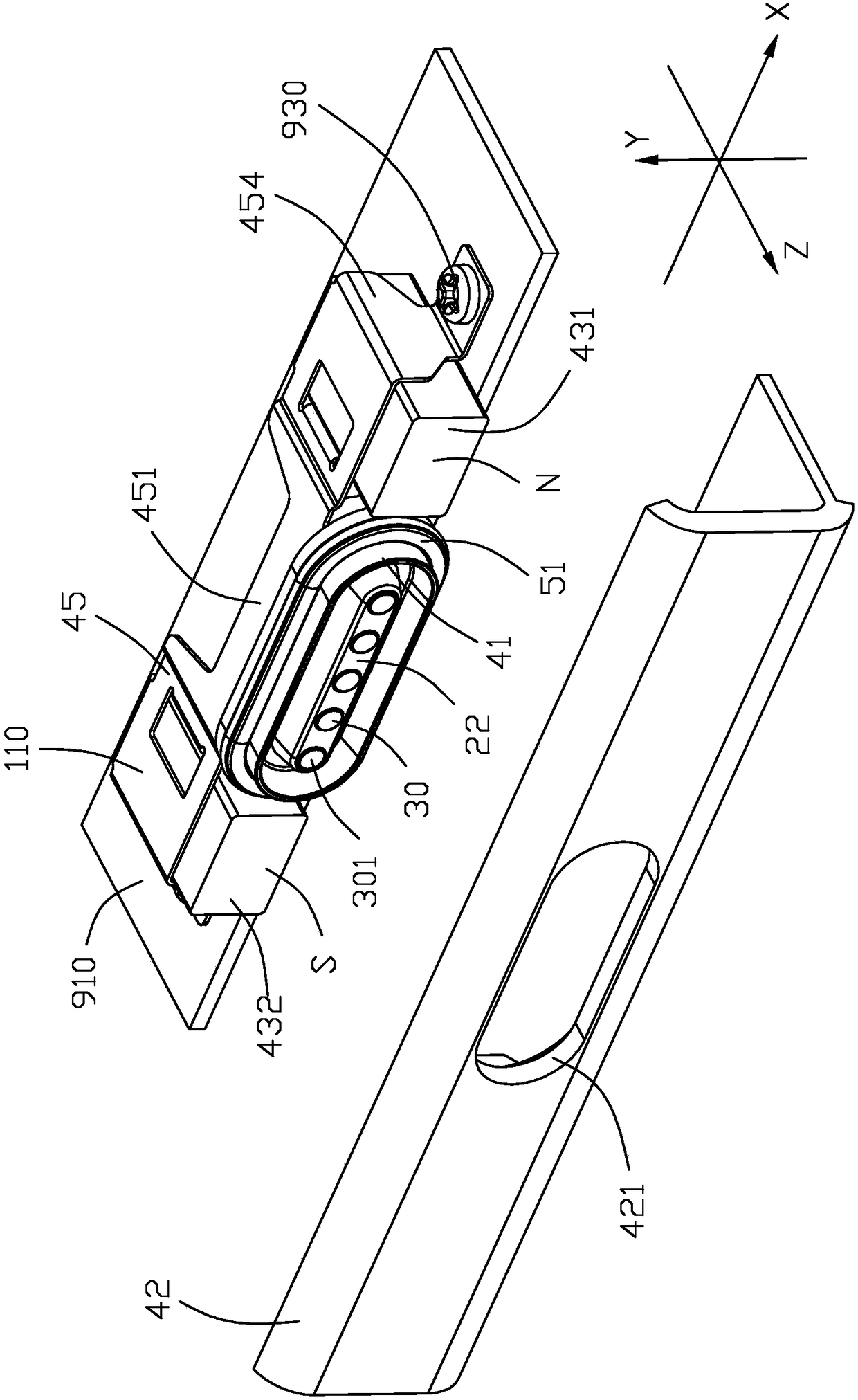
[0073] Below, will combine Figure 1 to Figure 16 The specific implementation manner of the magnetic suction connector assembly 100 of the present invention is introduced. The direction of the description of the present invention is based on figure 1 As a reference, define an X-axis extending in the left-right direction, a Y-axis perpendicular to the X-axis and extending in the up-down direction, and a Z-axis perpendicular to the X-axis and the Y-axis and extending in the front-rear direction. The X-axis arrow points to the left direction, the Y-axis arrow points to the upward direction, and the Z-axis arrow points to the front direction.

[0074] Please refer to Figure 1 to Figure 15 As shown, the present invention provides a magnetic connector assembly 100 including a receptacle connector 110 and a plug connector 120 . Figure 1 to Figure 15 It is the first embodiment of the magnetic connector assembly 100 . The conductive terminals include the socket terminal 30 of the...


PUM


Abstract

The invention discloses a magnetic type connector. The magnetic type connector comprises an insulating body, a plurality of conductive terminals retained in the insulating body and magnetic elements located at two sides of the plurality of conductive terminals; the insulating body is provided with a butting region arranged at the front end, the plurality of conductive terminals are arranged in thebutting region and comprise contact parts exposed to the butting region; the magnetic type connector further comprises a metal shell arranged at the periphery of the butting region in an enclosing manner and surrounds the conductive terminals; the magnetic elements comprise a first magnetic element and a second magnetic element with opposite magnetic poles located at the two opposite sides of themetal shell; through the first magnetic element and the second magnetic element with the opposite magnetic poles, the magnetic type connector can only be butted in the positive direction, meanwhile,the conductive terminals accommodated in an accommodating space of the metal shell can be prevented from being interfered by external signals.

Description

【Technical field】 [0001] The invention relates to a magnetic suction connector combination, in particular to a magnetic suction connector combination that prevents reverse insertion. 【Background technique】 [0002] The U.S. Patent No. 7311526 published on December 25, 2007 discloses a magnetic electrical connector, which includes a socket end and a plug end docked with the socket end. The socket end is provided with two magnetic elements with different magnetic poles, and the plug end is provided with There is a magnetically conductive sheet, so that the plug end and the socket end can be magnetically fitted together in a forward or reverse direction, and it cannot be controlled by a magnetic element and prevents the plug end from magnetically fitting with the socket end in only one direction. In the pogo pin type connector disclosed in the Taiwan China Patent No. M486194 announced on September 11, 2014, the first plug-in part and the second plug-in part are respectively pro...

Claims


Application Information

Patent Timeline
Patent Type & Authority Applications(China)
IPC IPC(8): H01R13/64H01R13/642H01R13/62H01R13/648H01R13/52H01R12/72
CPCH01R12/727H01R13/5202H01R13/521H01R13/6205H01R13/64H01R13/642H01R13/648
Inventor 陈津佑庄顺荣
Owner FOXCONN (KUNSHAN) COMPUTER CONNECTOR CO LTD
Learn More