Remote carbon dioxide fire extinguisher
A carbon dioxide and fire extinguisher technology, applied in fire rescue and other fields, can solve problems such as limited injection kinetic energy, limited injection distance, and fire extinguishing in difficult-to-ignite areas
- Summary
- Abstract
- Description
- Claims
- Application Information
AI Technical Summary
Problems solved by technology
Method used
Image

Examples
Embodiment 1
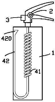
[0016] exist figure 1 In the first embodiment shown, the remote carbon dioxide fire extinguisher includes a main tank body 1, and the upper part of the main tank body 1 is provided with an opening and closing valve 2 and a nozzle 3; in the first embodiment, the opening and closing valve 2 is a nozzle valve , to facilitate intermittent injection.
[0017] The lower part of the opening and closing valve 2 is connected with an accelerating tube 41 extending into the main tank body 1. After the lower part of the accelerating tube 41 extends to the bottom of the main tank body 1, it is connected with an upwardly extending rising tube 42. A U-shaped tube is formed between the acceleration tube 41 and the riser tube 42; in the first embodiment, the riser tube 42 extends upwards close to the top of the main tank body 1, and a cup opening 420 is formed at the upper end of the riser tube 42, so that The carbon dioxide liquid is easy to enter the riser pipe 42; during the specific opera...
Embodiment 2
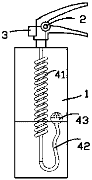
[0022] for figure 2 The real-time 2 shown is different from the embodiment 1 in that the riser 42 is a section of hose, the upper end of which is connected to a hollow float 43 that can float on the carbon dioxide liquid surface, and the riser 42 is connected to the hollow buoy. The hollow inner cavity of the ball 43; in a static state, the part of the floating ball 43 above the liquid surface is provided with a through hole.
[0023] According to Embodiment 2, if remote fire extinguishing is not required, it is only necessary to keep the opening and closing valve 2 open, and then the nozzle 3 continues to eject carbon dioxide gas to carry out close-range fire extinguishing; Open, and every time the main tank body 1 is shaken, the hollow float 43 vibrates on the carbon dioxide liquid surface, causing a small amount of carbon dioxide liquid to enter the riser 42 and the acceleration tube 41 through the through hole on the surface of the hollow float 43. In this way, the small...
Embodiment 3
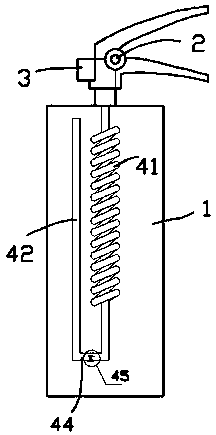
[0025] exist image 3 , Figure 4 In the third embodiment shown, different from the first embodiment, the riser pipe 42 extends upwards close to the top of the main tank body 1, and there is a section of horizontal transition pipe 44 between the riser pipe 42 and the acceleration pipe 41. The horizontal transition pipe 44 has a horizontal bottom, and a special valve 45 is arranged in the center of the horizontal bottom; the special valve 45 is as Figure 4 As shown, it includes a valve rod 451 that passes through the horizontal bottom and can freely slide up and down. The lower end of the valve rod 451 is connected to a valve plate 452, and the upper end of the valve rod 451 is connected to a wing-shaped floating plate 453; The horizontal bottom has liquid inlet holes (not shown) around the valve stem 451. When the valve stem 451 rises to the upper limit position, the valve plate 452 covers each of the liquid inlet holes so that the main tank The carbon dioxide liquid at the...
PUM
 Abstract
Description
Claims
Application Information
 - R&D
- Intellectual Property
- Life Sciences
- Materials
- Tech Scout
- Unparalleled Data Quality
- Higher Quality Content
- 60% Fewer Hallucinations
Browse by: Latest US Patents, China's latest patents, Technical Efficacy Thesaurus, Application Domain, Technology Topic, Popular Technical Reports.
© 2025 PatSnap. All rights reserved.Legal|Privacy policy|Modern Slavery Act Transparency Statement|Sitemap|About US| Contact US: help@patsnap.com