Magnetic impact type gravity center transfer system

A transfer system and center of gravity technology, applied in fishing, application, artificial fish bait, etc., can solve the problems of short flight distance, high energy loss, multi-kinetic energy, etc., and achieve high fish rate, strong practicability, and stable attitude Effect

Pending Publication Date: 2019-08-16
李海洋
View PDF1 Cites 0 Cited by
  • Summary
  • Abstract
  • Description
  • Claims
  • Application Information

AI Technical Summary

Problems solved by technology

[0003] The first type is the steel ball sliding center of gravity transfer system. There is an "S"-shaped slideway inside the lure bait, and a steel ball inside the slideway. At the moment of throwing down, the steel ball on the "S"-shaped slideway It hits the tail of the slideway, and after falling into the water, it is positioned again in the bending section of the "S" slideway, so as to provide kinetic energy for the lure bait and make the lure bait fly farther; but because the steel ball itself is lighter in weight and The steel ball will lose more kinetic energy when sliding out of the turning section of the "S" slideway, so the steel ball itself can not provide huge kinetic energy for the lure bait to make it fly farther
[0004] The second type is the tungsten column sliding center of gravity transfer system. A straight slide rail is set inside the lure bait. A thin steel wire is connected to both ends of the straight slide rail. A tungsten column is set on the thin steel wire. The thin steel wire is close to the road. There is a spring installed at one end of the tail of the lure. When the lure is thrown, when the tungsten column hits the tail of the lure along the thin steel wire, the kinetic energy of the tungsten column is mostly converted into the compression kinetic energy of the spring, and part of it is converted into lure through the spring. The kinetic ...

Method used


Image

  • Magnetic impact type gravity center transfer system
  • Magnetic impact type gravity center transfer system
  • Magnetic impact type gravity center transfer system

Examples


Embodiment Construction

[0019] In order to make the object, technical solution and advantages of the present invention clearer, the present invention will be further described in detail below in conjunction with the accompanying drawings and embodiments. It should be understood that the specific embodiments described here are only used to explain the present invention, not to limit the present invention.

[0020] It should be noted that when an element is referred to as being “fixed on” or “disposed on” another element, it may be directly on the other element or there may be an intervening element at the same time. When an element is referred to as being "connected to" another element, it can be directly connected to the other element or intervening elements may also be present.

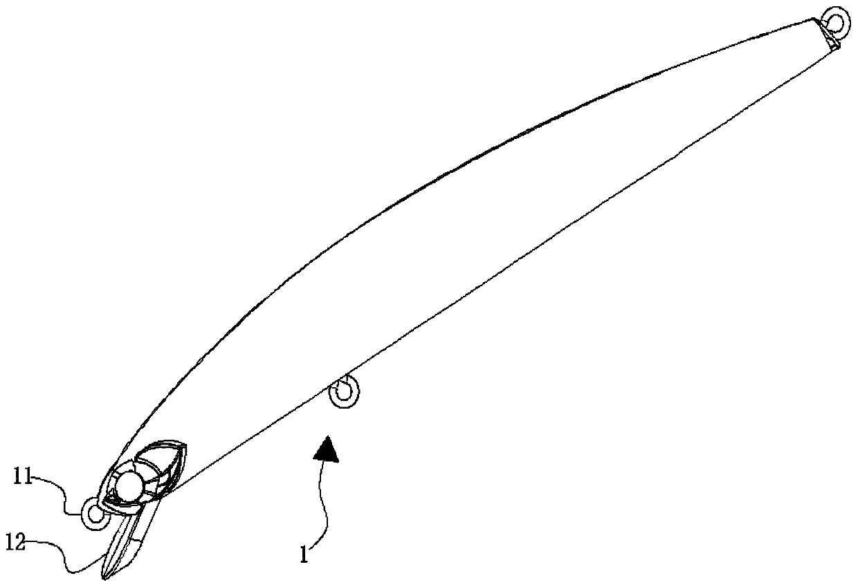
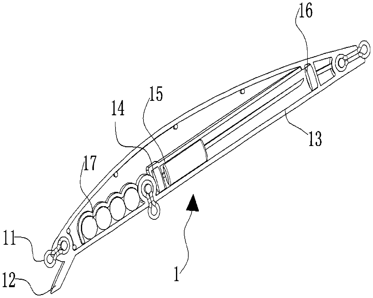
[0021] The present invention is achieved in this way, a magnetic impact type center of gravity transfer system, the magnetic impact type center of gravity transfer system includes a lure bait body 1; a straight slideway 13 ...


PUM


Abstract

The invention relates to the technical field of fishing gear, in particular to a magnetic impact type gravity center transfer system. The system comprises a lure bait body, wherein a straight slide isformed in the lure bait body; a magnet block is arranged at one end, close to the head of the lure bait body, of the straight slide; a heavy column capable of being attracted by the magnet block is arranged in the straight slide. The straight slide is arranged in the lure bait body, by cooperation of the magnet block and the heavy column in the straight slide, during throwing of the lure bait body, the heavy column is separated from adsorption of the magnet block and impacts the tail of the lure bait body along the straight slide at a high speed under the centrifugal force of instant separation, the flying posture of the lure bait in the air is more stable under the push of the enormous impact kinetic energy, the flying distance is longer, people can search water areas on a larger scale during fishing, large fishes in the distance can be reached, the fishing rate of a lure bait is greatly increased, and the system is high in practicability.

Description

technical field [0001] The invention relates to the technical field of fishing gear, in particular to a magnetic impact type center of gravity transfer system. Background technique [0002] Lure is a fishing method, named from the transliteration of Lure, that is, fishing with false bait, which is a method of imitating weak creatures to trigger big fish to attack. As a kind of bionic bait, lure bait is often used in lure fishing methods. In the practical application of lure baits, a center of gravity transfer system is often installed in the body of the lure bait to increase the flying distance of the lure bait in the air, so that the lure bait body can be cast to a farther landing point. The existing center of gravity transfer systems are mainly divided into the following three categories: [0003] The first type is the steel ball sliding center of gravity transfer system. There is an "S"-shaped slideway inside the lure bait, and a steel ball inside the slideway. At the m...

Claims


Application Information

Patent Timeline
IPC IPC(8): A01K85/12
CPCA01K85/12
Inventor 李海洋
Owner 李海洋
Why Eureka
Try Eureka