

Fixed-wing unmanned airplane takeoff method
A technology of unmanned aerial vehicles and fixed wings, applied in the field of aircraft, can solve the problems affecting the endurance time and flight attitude, and achieve the effect of light weight, not easy to shake, and prolong the endurance time
- Summary
- Abstract
- Description
- Claims
- Application Information
AI Technical Summary
Problems solved by technology
Method used
Image

Examples
Embodiment 1
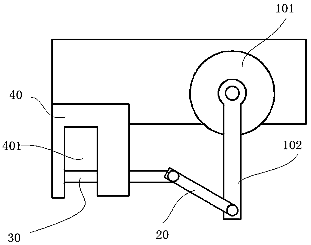
[0038] Such as figure 1 As shown, this embodiment provides a drone release mechanism, including: steering gear 101: steering gear 101 includes an output shaft; steering wheel 102: one end of the steering wheel 102 is fixedly connected to the output shaft; transmission rod 20: one end of the connecting rod 60 The other end of the rudder plate 102 is hinged with the latch rod 30: one end of the latch rod 30 is hinged with the other end of the connecting rod; the mounting block 40: the mounting block 40 is fixedly installed on the steering gear 101, and the middle part of the mounting block 40 is provided with a card slot 401, and the mounting block 40 A through hole 402 is provided in the horizontal direction, and the other end of the latch rod 30 extends through the through hole 402 into the slot 401. The inner wall of the slot 401 away from the steering wheel 102 is against the other end of the latch rod 30, and the steering gear 101 can drive the latch rod. 30 reciprocates in...
Embodiment 2
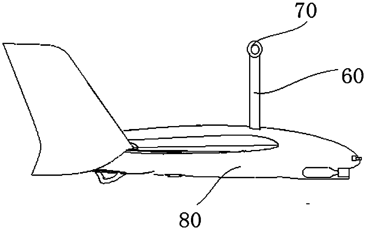
[0043] Such as figure 2 As shown, the present embodiment provides a fixed-wing unmanned aerial vehicle, including the unmanned aerial vehicle release mechanism of embodiment 1; The other end of the connecting rod 60 is provided with a hanging ring 70;
[0044] Both the multicopter and the fixed-wing aircraft 50 structures are prior art.
[0045] The multi-axis aircraft and the fixed-wing aircraft 50 are connected through the unmanned aerial vehicle release mechanism. The fixed-wing aircraft 50 is hung on the latch rod 30 in the card slot 401 through the hanging ring 70 provided on the connecting rod 60 , and controlled by the steering gear 101. The rotation of the multi-axis aircraft and the fixed-wing aircraft 50 can be flexibly and quickly realized the switching between the fixation and release of the multi-axis aircraft and the fixed-wing aircraft 50, and the separation of the multi-axis aircraft and the fixed-wing aircraft 50 can be realized during flight, thereby avoidi...
Embodiment 3
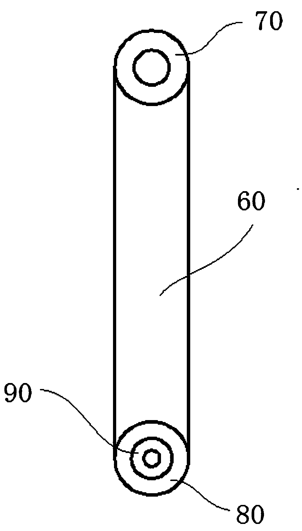
[0047] Such as image 3 As shown, the present embodiment provides a fixed-wing unmanned aerial vehicle, including the unmanned aerial vehicle release mechanism of embodiment 1; The other end of the connecting rod 60 is connected with the aircraft 50, and the other end of the connecting rod 60 is provided with a hanging ring 70; the steering wheel 102 is fixedly connected with the multi-axis aircraft, and the hanging ring 70 is located in the slot 401 and is sleeved on the latch rod 30; it also includes a fixing ring 80 and a carbon fiber sleeve 90, the fixed ring 80 is fixedly installed on one end of the connecting rod 60, the carbon fiber sleeve 90 is arranged symmetrically on the fixed wing 50, the axis of the carbon fiber sleeve 90 is perpendicular to the axis of symmetry of the fixed wing 50, the inner wall of the fixed ring 80 is aligned with the carbon fiber sleeve The outer wall of the tube 90 is connected.
[0048] The carbon fiber casing 90 arranged on the fixed-wing...
PUM
 Abstract
Description
Claims
Application Information