[0075]Another
advantage of the present invention is that the design of stimulators with many outputs may be simplified; this applies in particular to implanted stimulators. In the prior art, stimulators with multiple outputs are provided with an independent
voltage or
current source for each output, or alternatively with fewer
voltage or current sources than the number of outputs, and a relatively low bandwidth means of
multiplexing these sources to the outputs. In the former case, independent control of each output provides flexibility over the mapping of the notional stimulation field which may be provided by combining any number of available electrodes to produce the desired stimulation. However, the complexity of providing multiple outputs (typically sixteen or seventeen) is such that the voltage or current sources are typically constructed using
analogue electronics in order to minimise
space requirements, to satisfy the present trend towards smaller implants for ease of implantation. Analogue methods have the
advantage that they can be implemented on
chip and are therefore compact, but they have the
disadvantage that they are inefficient, which wastes battery power. In the case where a few voltage or current sources are multiplexed onto many outputs, the few voltage or current sources may be constructed using switching
electronics, such as switch-mode power supplies. This is efficient but bulky because external inductors or capacitors are required for each supply. This method has the
disadvantage that the number of electrodes that can be controlled independently is limited by the number of current or voltage sources available.
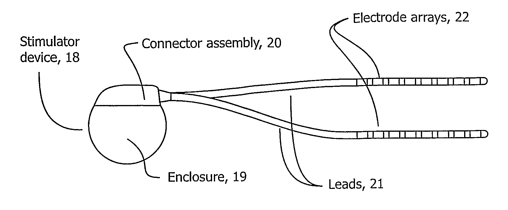
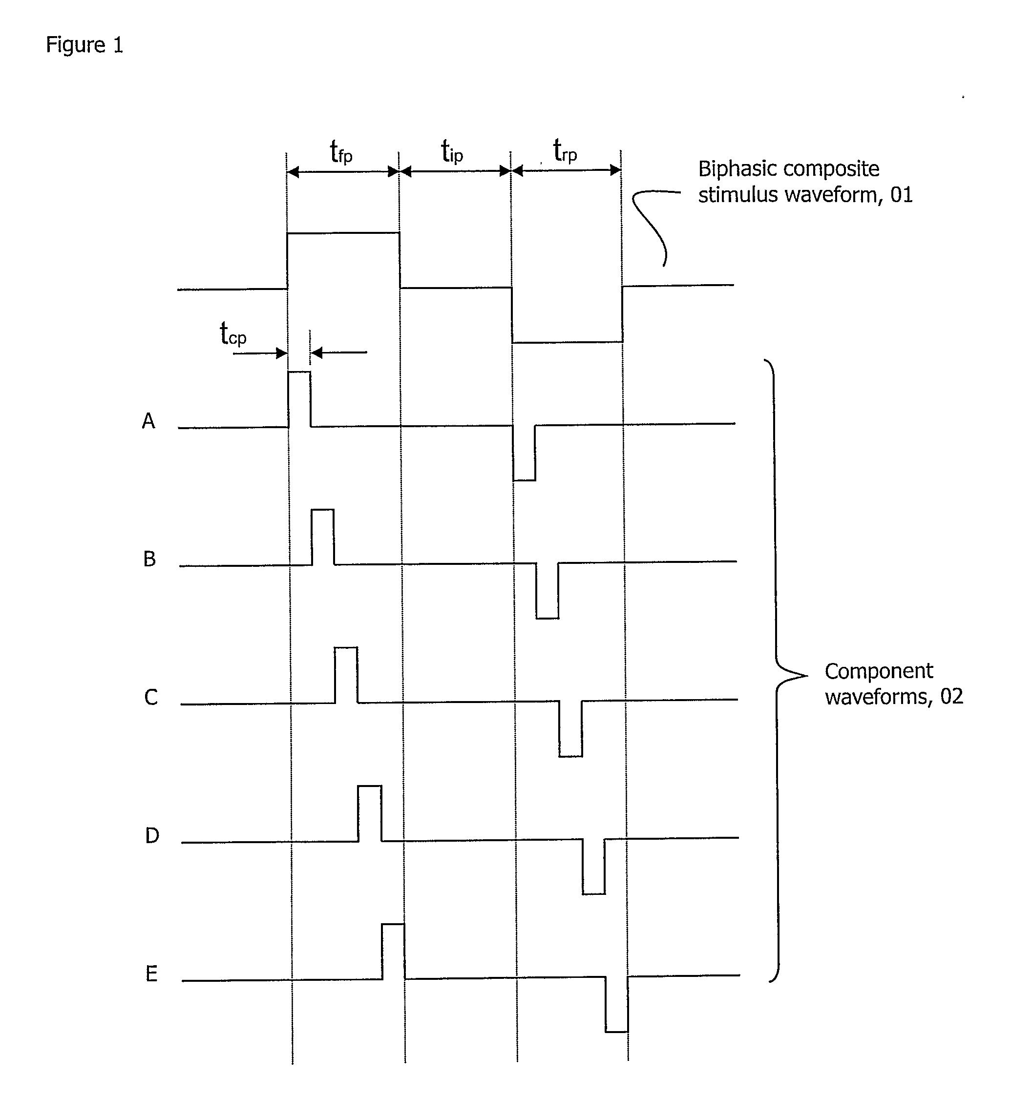
[0076]In its simplest physical realization, the invention may require only a single current, voltage, charge or
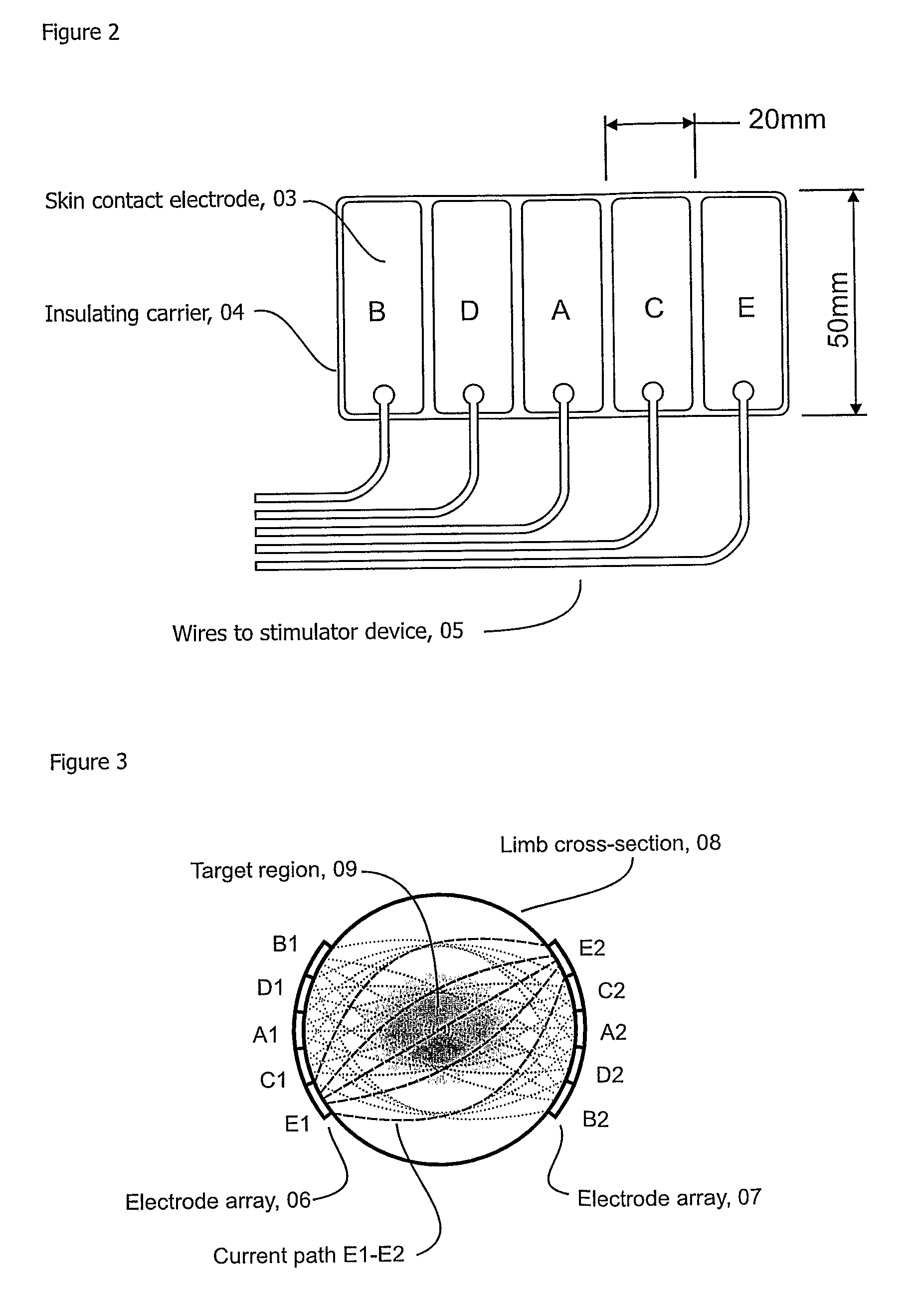
energy source to produce the desired composite pulse, which is then fed to a high speed switching network that breaks up the composite pulse into the component pulses that are applied to each
electrode pair. The paths of the component pulses intersect in the tissues to reconstruct the composite pulse. The
advantage of this method is that a single, efficient switching supply can be used, while providing independent control of the current or voltage applied to each
electrode in the array. Such an apparatus may be made more efficient than the analogue current sources described in the prior art, thereby increasing battery life, which is particularly important in implanted devices. Such an arrangement also has the advantage of being very compact, as the single switching supply can be designed to operate directly from the power source or battery.
[0077]Ideally the bandwidth of the switching supply should be high enough to allow the amplitude of the component pulses to be controlled over the period of each pulse, which may be of the order of one
microsecond. A
high bandwidth current source, with minimal
energy storage on the output side, or a means of either dissipating or regenerating into the battery
excess energy stored on the output of the supply is desirable, but difficult to realise in practice due to the very high
switching frequency required.
[0078]A simpler option is a fixed voltage supply, for instance fixed at the desired maximum output voltage of typically 15V in an
implanted device, where the average voltage on each component pulse is varied by modulation of the percentage of the time slice (i.e. the pulse width) allocated to each component pulse as a percentage of the total time available to each component pulse by control of the switching times on the switching network. Feedback of current flowing during the application of the component pulse may be used to control this modulation, thereby controlling
average current delivered during the pulse.
[0079]An improvement on the above is to provide a variable voltage supply, with relatively low bandwidth and consequently relatively low
switching frequency, such that the voltage is essentially fixed during the period of the component pulse. The effective amplitude of each component pulse is then adjusted by modulating the component pulse width as described above, either to achieve a desired
average current level, voltage or charge per pulse.
[0080]A further variation is to employ a variable amplitude power supply, for example a voltage supply, and a sensor or sensors that measure the current and / or voltage for each component or sub-component pulse (either by averaging these throughout a pulse or by sampling them one or more times), then feed back this data to modify the relative duty cycles of the component pulses so as to achieve the desired
average current, voltage, charge or
energy distribution among the respective electrode pairs and to modify the overall amplitude of the power supply to achieve the desired average current, voltage, charge or energy in the composite pulse as a whole. The
feedback loop may be implemented in the conventional way by applying correction to the respective duty cycles in real time, or on a cycle-by-cycle basis by applying corrections to the next cycle on the basis of data from the previous cycle. The cycle-by-cycle method has the advantage that the corrections may be calculated using a relatively low performance
microprocessor in the time between each cycle, whereas the real time method requires either analogue feedback or fast digital processors. The cycle-by-cycle feedback method is unable to compensate for variation in load impedance that occurs over the period of the
stimulus pulse, but in practice impedance varies only relatively slowly so this is not a significant disadvantage.

