Power bearing structure for an unmanned aerial vehicle

A load-bearing structure, UAV technology, applied in the field of UAVs, can solve problems such as interfering with the flight attitude of UAVs and detrimental to the escape of trapped persons.

Inactive Publication Date: 2019-01-04
EWATT TECH CO LTD
View PDF4 Cites 1 Cited by
  • Summary
  • Abstract
  • Description
  • Claims
  • Application Information

AI Technical Summary

Problems solved by technology

[0005] The technical problem to be solved by the present invention is that the UAV cannot shoot at the glass doors

Method used


Image

  • Power bearing structure for an unmanned aerial vehicle
  • Power bearing structure for an unmanned aerial vehicle
  • Power bearing structure for an unmanned aerial vehicle

Examples


Embodiment Construction

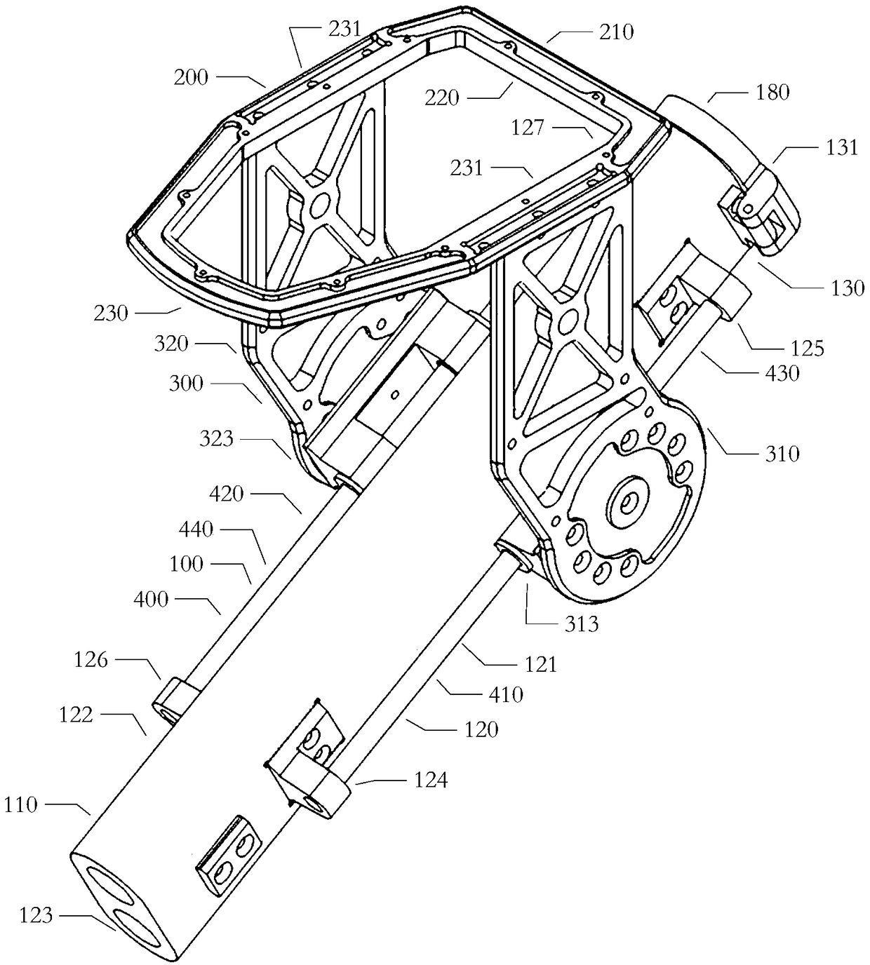
[0027]The present invention provides a dynamic load-bearing structure for an unmanned aerial vehicle. The first end of the first support arm is fixedly connected to the first clamping seat, and the third end of the second support arm is fixedly connected to the second clamping seat. . A first mounting hole and a first limiting area are provided on the second end, and a second mounting hole and a second limiting area are provided on the fourth end. Pass the first limiting rod in the shock absorbing part through the first installation hole provided on the second end of the first support arm, and the first elastic component is sleeved on the outside of the first limiting rod, so that the first elastic component is located Between the first fastening end and the second fastening end; the second limit rod in the shock-absorbing component passes through the second installation hole on the fourth end of the second support arm, and the second elastic component is sleeved on the second...


PUM


Abstract

The invention discloses a power bearing structure for an unmanned aerial vehicle, belonging to the technical field of the unmanned aerial vehicle, comprising a bearing component, a shock absorbing component and a power mechanism. The load bearing member includes a first support arm and a second support arm. The shock absorbing member includes a first stop lever, a second stop lever, a first resilient assembly, and a second resilient assembly. The first elastic assembly is sleeved on the exterior of the first limit lever, and the second elastic assembly is sleeved on the exterior of the secondlimit lever. The power mechanism comprises a first steering gear and a second steering gear, and the first steering gear comprises a first housing and a first rotating shaft; the second steering gearincludes a second housing and a second shaft. The invention can shoot the glass doors and windows at any time when the unmanned aerial vehicle is in various flight positions. Reducing the recoil forceproduced by shooting and stabilizing the flight attitude of unmanned aerial vehicle (UAV) are beneficial to the technical effect of helping the trapped people to escape in high-rise residential buildings in time.

Description

technical field [0001] The invention belongs to the technical field of drones, in particular to a dynamic load-bearing structure for drones. Background technique [0002] Unmanned UAV, referred to as "UAV", is an unmanned UAV controlled by radio remote control equipment and its own program control device. There is no cockpit on board, but it is equipped with autopilot, program control device, information collection device and other equipment. The personnel on the ground, on the ship, or at the remote control station of the parent aircraft track, locate, remotely control, telemeter and digitally transmit it through radar and other equipment. It can take off like an ordinary UAV under radio remote control or be launched into the air with a booster rocket, or it can be brought into the air by the parent aircraft for flight. [0003] For the unmanned aerial vehicle, the unmanned aerial vehicle fuselage in the prior art is made of a one-piece structure. The drone is mainly com...

Claims


Application Information

Patent Timeline
IPC IPC(8): B64D1/02B64C17/00
CPCB64C17/00B64D1/02
Inventor 不公告发明人
Owner EWATT TECH CO LTD
Why Eureka
Try Eureka