Downhole power generation device for water injection well

A technology for power generation devices and water injection wells, which is applied in wellbore/well valve devices, electromechanical devices, hydroelectric power generation, etc. It can solve the problems of large power generation devices, increased costs, and small fluid kinetic energy, and achieve enhanced mechanical strength and stability. performance, improve power generation efficiency, and simplify the transmission structure

Pending Publication Date: 2021-09-07
SHAANXI YANCHANG PETROLEUM JINSHI DRILLING EQUIP CO LTD
View PDF0 Cites 0 Cited by
  • Summary
  • Abstract
  • Description
  • Claims
  • Application Information

AI Technical Summary

Problems solved by technology

The traditional water injection method cannot solve the contradiction between layers, and at the same time, the water absorption capacity of each reservoir is different, so layered water injection is adopted by more and more oil fields
Most of the existing power supply schemes for water injection layered measurement and adjustment use cable power supply. The disadvantage is that the high temperature and high pressure environment in the well makes the cable prone to failure. Another power supply method is battery power supply, but because the battery is disposable, it needs to be regularly Replacement, which increases the cost and is not environmentally friendly, therefore, the use of turbine generators to generate electricity can solve the above problems
[0003] In the prior art, the existing downhole turbine generator is mainly used for large flow power generation, which is generally suitable for drilling and uses a large amount of mud discharged during drilling operations as a power source. This type of generator generally does not have strict volume restrictions, so the power generation Generally larger
However, due to the narrow underground space of the water injection well, the power generation device is large in size and cannot occupy the main water injection channel, otherwise it will affect the normal water injection. Moreover, the water injection volume of the water injection well is limited, and the fluid kinetic energy is small, so the power generation efficiency of driving the large flow power generation device extremely low

Method used


Image

  • Downhole power generation device for water injection well
  • Downhole power generation device for water injection well
  • Downhole power generation device for water injection well

Examples


Embodiment 1

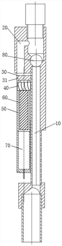
[0042] See figure 1 , an underground power generation device for a water injection well, comprising: a generator body arranged on the water outlet of the branch channel 20 on the side of the main water injection channel 10 in the well. One side of the water injection main channel 10 is provided with a branch channel 20 , the water inlet of the branch channel 20 communicates with the water injection main channel 10 , and the water outlet of the branch channel 20 is provided with a generator body. The main water injection channel 10 is provided with a plug 80 below the water inlet of the branch channel 20. When power generation is required, the plug 80 can block the main water injection channel 10, and the water flow entering the main water injection channel 10 can enter from the branch channel 20. Thus acting on the generator body, the generator body is started to generate electricity.

[0043] The generator body of this embodiment is arranged on the side of the main water inj...

Embodiment 2

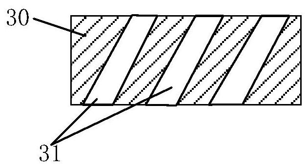
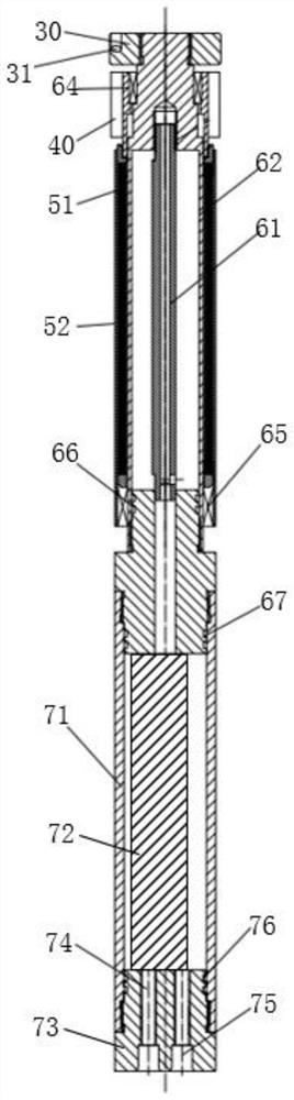
[0052] Such as image 3 As shown, on the basis of the first embodiment, this embodiment further defines that the outer rotor assembly 50 includes: a permanent magnet 51 and a rotor casing 52 . The inner stator assembly 60 includes: a stator core 61 and a stator shell 62 . The stator casing 62 is installed in the rotor casing 52, one end of the stator casing 62 is fixedly connected with the deflector plate 30 and rotatably connected with the turbine 40, and the other end of the stator casing 62 is fixedly connected with the power generation circuit assembly 70 and connected with the other end of the rotor casing 52. One end swivels to connect. The stator core 61 is fixed inside the stator shell 62 . The stator core 61 is screwed to the stator housing 62 . The permanent magnet 51 is fixed on the inner wall of the rotor housing 52 , and the permanent magnet 51 is located between the rotor housing 52 and the stator housing 62 . One end of the rotor housing 52 is fixedly connec...


PUM


Abstract

The invention discloses a downhole power generation device for a water injection well. The downhole power generation device comprises a power generator body arranged on a water outlet of a branch channel on one side of underground downhole water injection main channel; the power generator body comprises a flow guide disc, a turbine, an outer rotor assembly, an inner stator assembly and a power generation circuit assembly; a plurality of flow guide through holes are formed in the flow guide disc; the turbine is rotationally connected with the inner stator assembly; one end of the outer rotor assembly is fixedly connected with the turbine; the power generation circuit assembly is fixedly connected with the inner stator assembly; and a blanking plug is arranged below the water injection main channel close to a water inlet of the branch channel. The power generator body does not occupy the water injection main channel, and normal water injection is not affected. According to the power generator body, the kinetic energy of fluid beams acting on blades can be increased through the flow guide disc, so that the energy of water flow is fully utilized, and the power generation efficiency is improved.

Description

technical field [0001] The invention belongs to the technical field of downhole layered water injection equipment for water injection wells in oil fields, and in particular relates to an underhole power generation device for water injection wells. Background technique [0002] At each stage of oilfield development, water can be injected from the wellhead into the reservoir through the water injection well, so that each oil layer has a strong driving force to increase the recovery rate and production speed. The traditional water injection method cannot solve the contradiction between layers, and the water absorption capacity of each oil reservoir is different, so layered water injection is adopted by more and more oil fields. Most of the existing power supply schemes for water injection layered measurement and adjustment use cable power supply. The disadvantage is that the high temperature and high pressure environment in the well makes the cable prone to failure. Another pow...

Claims


Application Information

Patent Timeline
Patent Type & Authority Applications(China)
IPC IPC(8): E21B43/20E21B34/06F03B13/02F03B3/18F03B3/12H02K7/18H02K1/12H02K1/27
CPCE21B43/20E21B34/06F03B13/02F03B3/18F03B3/126H02K7/1823H02K1/2786H02K1/12Y02E10/20
Inventor 郑向勇李佳隆秦宏伟邵金海
Owner SHAANXI YANCHANG PETROLEUM JINSHI DRILLING EQUIP CO LTD
Why Eureka
Try Eureka