Eureka AIR delivers breakthrough ideas for toughest innovation challenges, trusted by R&D personnel around the world.

Catalytic device for pollutants

A catalytic device and pollutant technology, which is applied to mixers with rotary stirring devices, transportation and packaging, chemical instruments and methods, etc., can solve the problems of inability to contact catalysts with polluting particles, insignificant catalytic effect, waste of time and cost, etc. , to achieve the effect of improving the catalytic reaction speed, protecting the device and increasing the amount of dissolved oxygen

Inactive Publication Date: 2018-07-27
楼一
View PDF0 Cites 0 Cited by
  • Summary
  • Abstract
  • Description
  • Claims
  • Application Information

AI Technical Summary

Problems solved by technology

[0002] In industrial production, more pollution particles are often produced, and these pollution particles take a long time to degrade. Therefore, catalysts are often used to accelerate the reaction. Traditionally, for this operation, the catalyst is usually directly sprinkled on the surface of the pollution particles , however, this method of operation cannot completely contact the catalyst with the pollution particles, making the catalytic effect extremely inconspicuous, wasting a lot of time and cost, and having major defects

Method used

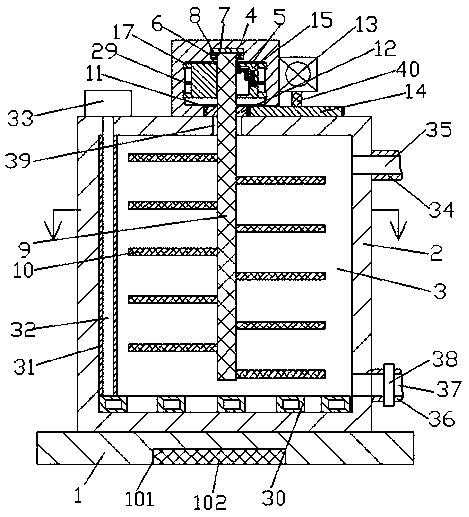

Image

  • Catalytic device for pollutants
  • Catalytic device for pollutants
  • Catalytic device for pollutants

Examples


Embodiment Construction

[0014] The following will clearly and completely describe the technical solutions in the embodiments of the present invention with reference to the accompanying drawings in the embodiments of the present invention. Obviously, the described embodiments are only some, not all, embodiments of the present invention. Based on the embodiments of the present invention, all other embodiments obtained by persons of ordinary skill in the art without making creative efforts belong to the protection scope of the present invention.

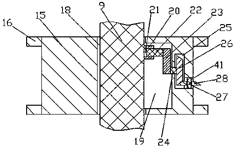
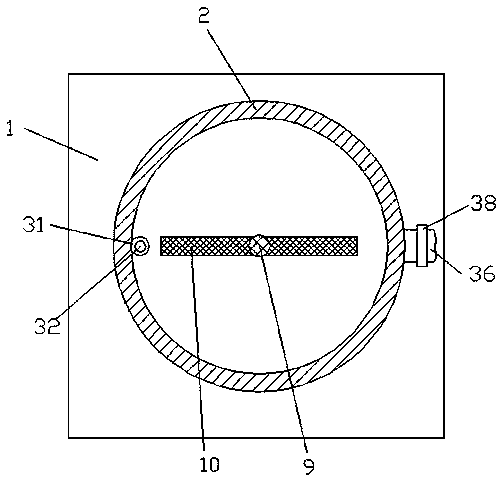
[0015] see Figure 1-Figure 5 , an embodiment provided by the present invention: a catalytic device for pollutants, including a bottom plate 1 and a catalytic box 2, a counterweight groove 101 is provided at the inner bottom of the bottom plate 1, and a counterweight groove 101 is fixed in the counterweight groove 101. Weight 102, the counterweight 102 is used to increase the bottom weight of the bottom plate 1, thereby increasing the stability of the support ...


PUM


Abstract

The invention discloses a catalytic device for pollutants. The device comprises a bottom plate and a catalytic tank, the bottom of the bottom plate is provided with a counterweight groove, the interior of the counterweight groove is fixedly provided with a counterweight block, the interior of the catalytic tank is provided with a stirring chamber, a mounting box is fixedly connected with the middle end position of the upper end surface of the catalytic tank, the interior of the mounting box is provided with a mounting chamber, a plurality of stirring arms are fixedly connected with a rotatingcolumn, the right end surface of the mounting box is fixedly connected with a motor, the motor is fixedly connected with a first toothed wheel through an output shaft located at the lower end of the motor, and the left end of the first toothed wheel is located in a hollow tank and is in cooperative connection with a second toothed wheel.

Description

technical field [0001] The invention relates to the field of catalytic equipment, in particular to a catalytic device for pollutants. Background technique [0002] In industrial production, more pollution particles are often produced, and these pollution particles take a long time to degrade. Therefore, catalysts are often used to accelerate the reaction. Traditionally, for this operation, the catalyst is usually directly sprinkled on the surface of the pollution particles However, this operation method cannot completely contact the catalyst with the pollution particles, making the catalytic effect extremely inconspicuous, wasting a lot of time and cost, and has relatively large defects. Contents of the invention [0003] The purpose of the present invention is to provide a catalytic device for pollutants, so as to solve the problems raised in the above-mentioned background technology. [0004] In order to achieve the above object, the present invention provides the follo...

Claims


Application Information

Patent Timeline
Patent Type & Authority Applications(China)
IPC IPC(8): B01J8/10B01J8/08B01F7/16B01F7/18
CPCB01J8/085B01J8/10B01F27/805B01F27/806B01F27/90
Inventor 楼一
Owner 楼一
Why Eureka
Eureka Blog
Learn More