Unlock instant, AI-driven research and patent intelligence for your innovation.
Wing spar die
What is Al technical title?
Al technical title is built by PatSnap Al team. It summarizes the technical point description of the patent document.
A technology of wing beams and molds, which is applied in the field of mechanical devices and transportation, can solve problems such as self-weight deformation and large positioning errors, and achieve the effects of improving process precision and quality, improving work efficiency, and ensuring positioning accuracy and stability
Active Publication Date: 2018-07-27
BEIJING AERONAUTIC SCI & TECH RES INST OF COMAC +1
View PDF6 Cites 1 Cited by
Summary
Abstract
Description
Claims
Application Information
AI Technical Summary
This helps you quickly interpret patents by identifying the three key elements:
Problems solved by technology
Method used
Benefits of technology
Problems solved by technology
[0007] The purpose of the present invention is to provide a spar mold, which can solve the problems of large positioning error and self-weight deformation of the prepreg plate during the positioning and moving process of the thermal diaphragm forming process, and reduce the uncertainty caused by the movement of the prepreg plate To ensure the positioning accuracy and stability of the prepreg slab during positioning and movement
Method used
Image
Click on the blue label to locate the original text in one second.
Reading with bidirectional positioning of images and text.
Examples
Embodiment 1
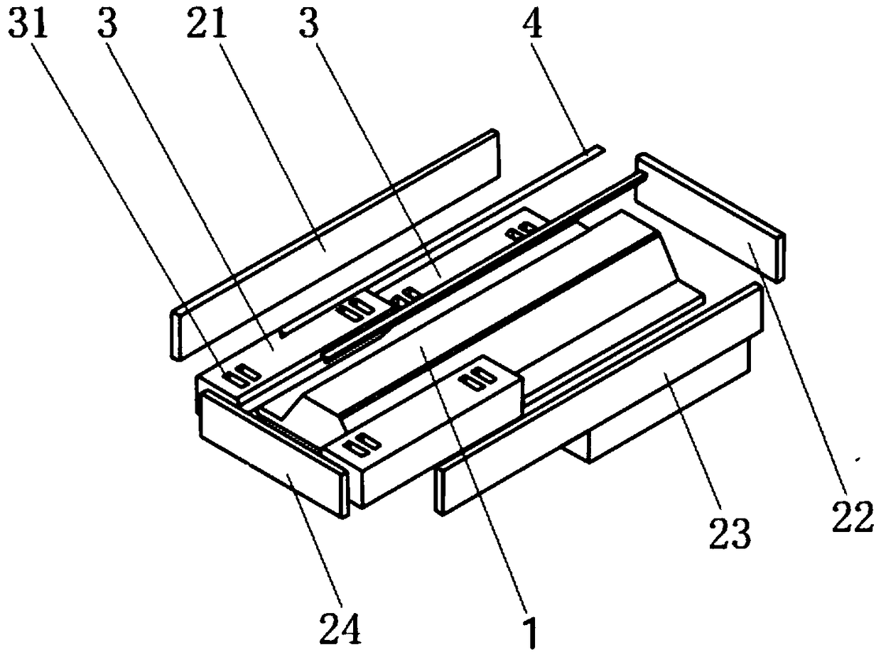
[0036] figure 2 It is an exploded perspective view of the spar mold provided by the present invention.
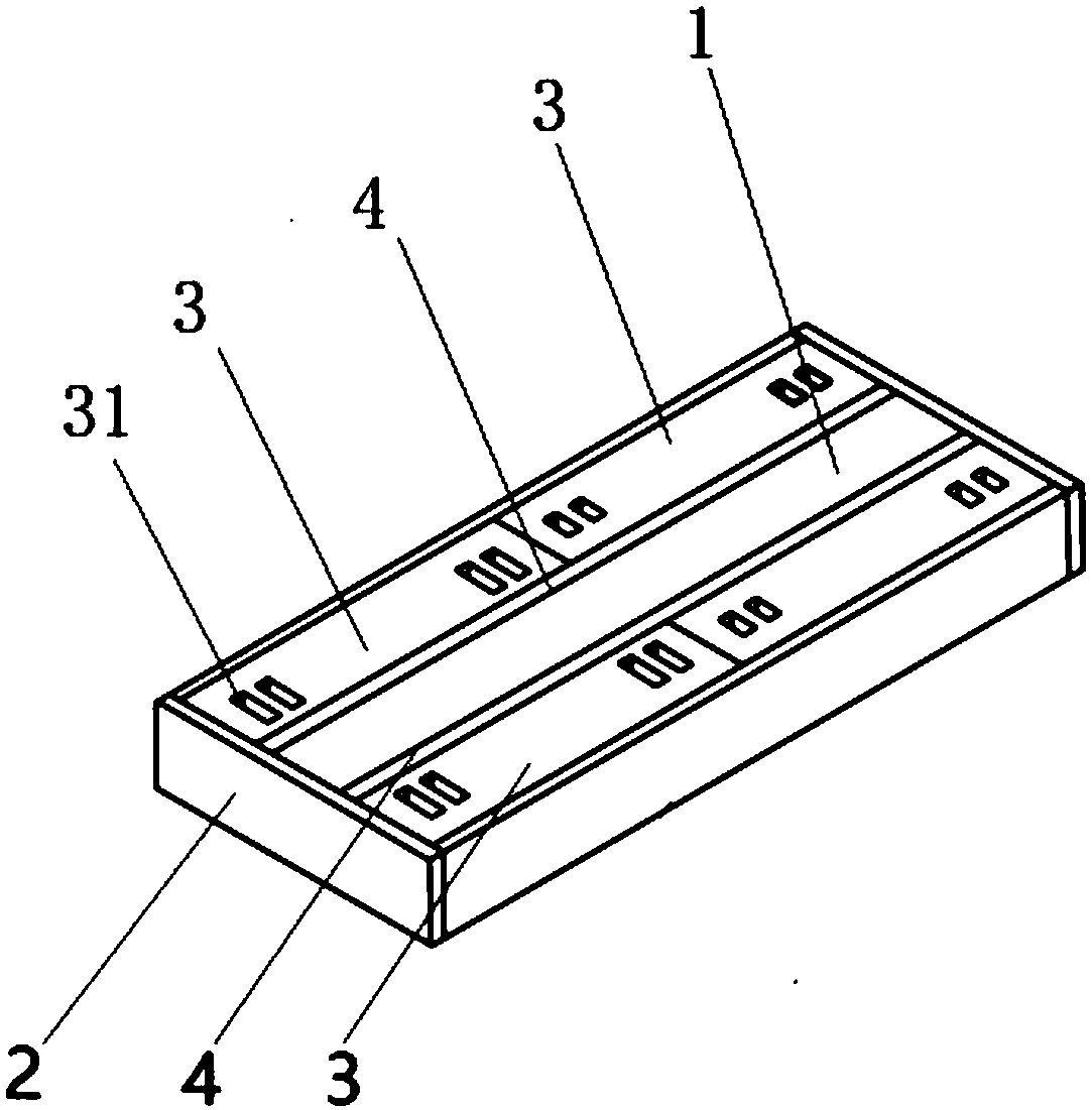
[0037] image 3 It is an assembly perspective view of the spar mold provided by the present invention.
[0038] Such as figure 2 , image 3 As shown, this embodiment provides a spar mold for the thermal diaphragm forming process of a composite spar, including: a forming boss 1 , a frame body 2 and a filling block 3 .
[0039] The forming boss 1 is used for forming the thermal diaphragm of the spar in the thermal diaphragm equipment to make it into the desired shape.
[0040] Optionally, the cross-sectional shape of the forming boss 1 is trapezoidal, C-shaped or arc-shaped.
[0041] The frame body 2 is detachably arranged around the forming boss 1, and is used to form a mold frame with shaping and force bearing functions.
[0042] Optionally, the cross section of the frame body 2 is rectangular, but the present invention is not limited thereto, and the cross section ...
Embodiment 2
[0068] Figure 5 It is a three-dimensional schematic diagram of the structure of the filling bar provided by the present invention.
[0069] Such as figure 2 , image 3 , Figure 5 As shown, the difference between this embodiment and Embodiment 1 is that, according to the actual situation, when there is a gap between the forming boss 1 and the filling block 3 due to the difference in shape, the spar mold also includes: filling strips 4.
[0070] The filling strip 4 is arranged in the gap formed between the forming boss 1 and the filling block 3 for filling the gap.
[0071] Optionally, the upper surface of the filling strip 4 is on the same plane as the upper surface of the forming boss 1 .
[0072] Optionally, the upper surface and the bottom surface of the filling bar 4 , the filling block 3 and the frame body 2 are all on the same height plane as the forming boss 1 .
[0073] Optionally, the filling strip 4 is integrally formed or arranged in sections, and its total ...
PUM
Abstract
The invention provides a wing spar die. The wing spar die is used for a forming process for the hot diaphragm of a wing spar made from a composite material. The wing spar die comprises a forming boss(1), a frame body (2) detachably arranged around the forming boss (1), and a filling block (3) arranged in the space formed by the forming boss (1) and the frame body (2), and the shape of the fillingblock (3) is matched with the shape of the space, so that the filling block (3) fills the space; and the upper surfaces of the frame body (2) and the filling block (3), and the upper surface of the forming boss (1) are located on the same plane. According to the wing spar die provided by the invention, the problems of large location error, dead-weight deformation and the like of a flat prepreg plate in location and movement processes in the forming process for the hot diaphragm are solved, the uncertainty influence brought by the movement of the flat prepreg plate is reduced, and the locationaccuracy and stability of the flat prepreg plate in the location and movement processes are guaranteed; and moreover, the die is scientific and reasonable in structure, and the combined detachment manner of the whole die is reasonable and easy to use, so that the use convenience of the die is improved, and the die is safe and convenient to operate.
Description
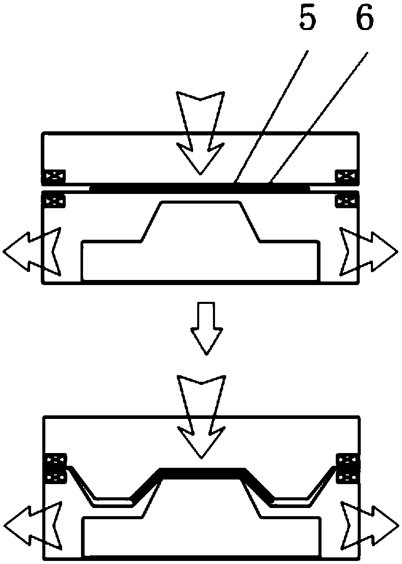
technical field [0001] The invention relates to the technical field of mechanical devices and transportation, in particular to a spar mold. Background technique [0002] Thermal diaphragm forming process: refers to the use of automatic tape laying or manual laying process to lay prepreg laminates for preforms, such as figure 1 As shown, the prepreg flat plate 5 is clamped between the superplastic membranes 6, the inside of the diaphragm is vacuumed, the temperature is raised, and the vacuuming operation is performed to make the prepreg layers slide, deform and stick to the mold, and finally the prepreg is laminated. To the surface of the mold, the preforming process is completed and the preform is prepared. [0003] Preform: A structure consisting of prepreg plies that have undergone the preforming process. The preform has a similar geometry to the final part. For complex parts, it can be assembled from different secondary preforms, or can be composed of secondary preform...
Claims
Application Information
Patent Timeline
Application Date:The date an application was filed.
Publication Date:The date a patent or application was officially published.
First Publication Date:The earliest publication date of a patent with the same application number.
Issue Date:Publication date of the patent grant document.
PCT Entry Date:The Entry date of PCT National Phase.
Estimated Expiry Date:The statutory expiry date of a patent right according to the Patent Law, and it is the longest term of protection that the patent right can achieve without the termination of the patent right due to other reasons(Term extension factor has been taken into account ).
Invalid Date:Actual expiry date is based on effective date or publication date of legal transaction data of invalid patent.
Patent Type & Authority Applications(China)
IPC IPC(8): B29C70/54B29C70/34B29C70/44
CPCB29C70/342B29C70/443B29C70/54B29C70/541
Inventor 谢汶轩高举斌肖志鹏孙见卓王栋刘传军
Owner BEIJING AERONAUTIC SCI & TECH RES INST OF COMAC
