
Pipe diameter adjusting mechanism

A technology for adjusting mechanisms and pipe diameters, which is applied to special pipes, pipe components, mechanical equipment, etc., can solve the problems of poor obstacle stability of robots, improve autonomous obstacle crossing capabilities, enhance the adaptability of the working environment, and improve stability Effect

Inactive Publication Date: 2018-07-27
NORTH CHINA UNIVERSITY OF SCIENCE AND TECHNOLOGY
View PDF14 Cites 19 Cited by
  • Summary
  • Abstract
  • Description
  • Claims
  • Application Information

AI Technical Summary

Problems solved by technology

Obviously, the robot's obstacle stability performance is poor

Method used


Image

  • Pipe diameter adjusting mechanism
  • Pipe diameter adjusting mechanism
  • Pipe diameter adjusting mechanism

Examples


Embodiment 1

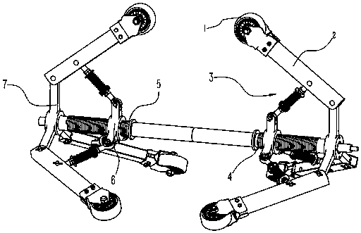
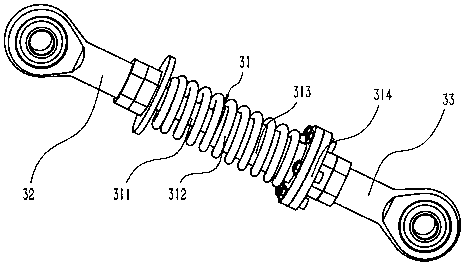
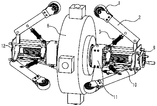
[0018] Such as figure 1 , image 3 , Figure 4 As shown, a pipe diameter adjustment mechanism includes a front radial adjustment device and a rear radial adjustment device that are basically the same in structure and symmetrically arranged on both sides of the detection device 8. Both of them use screw nut pairs to drive three groups of circumferentially evenly distributed Parallel link structure is used to achieve diameter reduction. This split structure overcomes the problem that the planar link mechanism hinders the rotational movement of the detection device, so that the detection device 8 can rotate freely. Each group of parallel connecting rod structures includes a flexible push rod 3 and a wheel leg 2. The middle part of the flexible push rod 3 is a buffer assembly 31, and the two ends are respectively a joint bearing 32 and a joint bearing 33. The flexible push rod 3 passes through the joint bearing 32 and the joint bearing 33. Joint bearing 33 is hinged with wheel l...

Embodiment 2

[0025] The pipe diameter adjustment mechanism in this embodiment is basically the same as the structure in Embodiment 1, the difference is that the adjustment hand wheel 9 is not installed on the right end of the adjustment screw 4 but is connected to the motor, and the resistance strain is arranged on the support wheel 1. piece. Therefore, the whole mechanism realizes the automatic adjustment of pipe diameter under the drive of the motor. When the resistance strain gauge detects that the pressure between the support wheel 1 and the pipe wall reaches the expected value, the motor stops rotating. In this way, the diameter reduction adjustment can also be implemented when the specific size of the pipe diameter cannot be known in advance.

[0026] In addition to being used in pipeline rotation detection robots, the invention can also be used in other pipeline rotation operations (such as pipeline spraying and pipeline joint repairing) robots that need to change diameters.


PUM


Abstract

The invention relates to a pipe diameter adjusting mechanism. The pipe diameter adjusting mechanism comprises two radial adjusting devices which are basically the same in structure and are symmetrically arranged on the two sides of a detecting device. The radial adjusting devices both adopt screw rod nut pairs to drive three parallel-connecting connecting rod mechanisms to achieve diameter changing, wherein the spaces of the three parallel-connecting connecting rod mechanisms are spaced by 120 degrees. Screw rods in the two radial adjusting devices are the same in screw pitch and rotation direction and are oppositely mounted, and the purpose of synchronous rotation is achieved through mutual cooperation of bosses and grooves in the connecting end faces. The pipe diameter adjusting mechanism can adapt to the pipe diameter change within a certain range, and all supporting wheels can independently cross obstacles without affecting the stability of the whole structure, so that the adaptivecapacity of the operation environment of the pipe diameter adjusting mechanism is greatly enhanced; stable support can be provided for the rotating-type pipeline detecting device, and thus the problems that in the prior art, rotating of the detecting device is obstructed, and the abnormal posture of the detecting device is prone to occurring are effectively solved; the structure is simple and convenient to adjust; and the pipe diameter adjusting mechanism can also be used in other pipeline rotating operation robots needing diameter changing.

Description

technical field [0001] The invention relates to the technical field of pipeline robots, in particular to a pipeline diameter adjustment mechanism of a pipeline rotation detection robot. Background technique [0002] A pipeline inspection robot refers to a robot that detects corrosion, cracks, etc. inside a pipeline by means of a certain detection device. For industrial pipelines, robots are more suitable for inspection methods that do not require couplants and can achieve non-contact measurements. However, during the detection process, the distance between the probe and the pipe wall and the attitude change of the probe will affect the measurement results. In addition, the diameter of the pipe to be tested is often not a single size, so the pipe inspection robot usually uses the screw nut pair to drive the parallel linkage to realize the diameter changing function to improve its pipe diameter adaptability. For example, Zhang Yunwei of Shanghai Jiaotong University proposed ...

Claims


Application Information

Patent Timeline
IPC IPC(8): F16L55/28F16L101/30
CPCF16L55/28F16L2101/30
Inventor 王丰何磊王鑫阁唐宇轩王宁
Owner NORTH CHINA UNIVERSITY OF SCIENCE AND TECHNOLOGY
Learn More