Laser measuring device and measuring method

A technology of laser measurement and laser head, which is applied in the direction of measuring devices, optical devices, instruments, etc., can solve problems such as large errors in measurement results, and achieve the effects of ensuring constant accuracy, improving work efficiency, and reducing rotation angles

Pending Publication Date: 2018-07-27
SF TECH
View PDF9 Cites 4 Cited by
  • Summary
  • Abstract
  • Description
  • Claims
  • Application Information

AI Technical Summary

Problems solved by technology

[0006] Thirdly, there are often many space dead zones in closed spaces or land trucks. Generally, the laser emitted by the measuring device installed at the bottom of the measured space cannot effectively avoid these space dead zones, resulting in large errors in measurement results. Therefore, it is necessary to develop A laser measuring device that can be installed on the top of the measured space is proposed, so that the laser measuring device can measure the measured space from top to bottom, which can effectively reduce the dead zone of the measured space and further improve the accuracy of the closed space. The measurement accuracy of the volume ratio or the loading ratio of the land freight car compartment

Method used


Image

  • Laser measuring device and measuring method
  • Laser measuring device and measuring method
  • Laser measuring device and measuring method

Examples


Embodiment 1

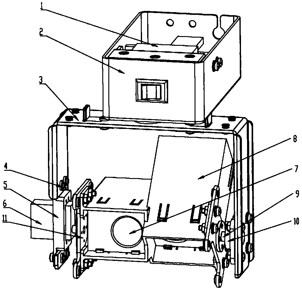
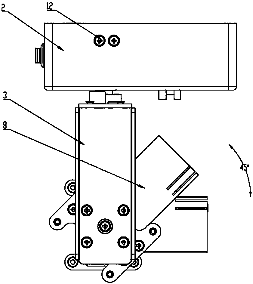
[0059] Such as Figure 1-Figure 3 As shown, the present embodiment provides a kind of laser measuring device, wherein, comprise laser emission mechanism, vertical rotation mechanism, horizontal rotation mechanism and support 3, vertical rotation mechanism, horizontal rotation mechanism and laser emission mechanism are installed on the support 3, vertical The rotating mechanism is connected with the laser emitting mechanism and drives the laser emitting mechanism to rotate, and the horizontal rotating mechanism is connected with the bracket 3 and drives the bracket 3 to rotate,

[0060] Whenever the horizontal rotation mechanism drives the bracket 3 to rotate from the horizontal initial position to the horizontal end position, the vertical rotation mechanism drives the laser emitting mechanism to rotate a predetermined angle from the current position in the vertical direction.

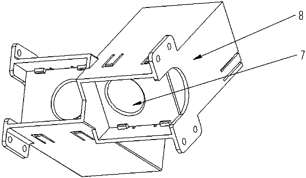
[0061] The laser emitting mechanism includes two laser heads 7, the laser heads 7 are installed in t...

Embodiment 2

[0099] The features of this embodiment that are the same as those of Embodiment 1 will not be described in detail. The features of this embodiment that are different from Embodiment 1 are:

[0100] The laser emitting mechanism includes three laser heads 7, the laser heads 7 are installed in the laser head bracket 8, the included angle between the three laser heads 7 is 30°, and the sum of the included angles of the three laser heads 7 is 90°.

[0101] The laser measuring device of the example of the second embodiment is installed on the top of the measured space through the control box 2, and after the suspension of the laser measuring device is completed, the horizontal rotation mechanism drives the bracket 3 to rotate on the horizontal plane, and the vertical rotation mechanism drives the laser emitting mechanism to The scanning measurement work on a vertical plane can be completed by turning down 30°.

[0102] Compared with the prior art that requires a laser head to rotate...


PUM


Abstract

The invention belongs to the technical field of space volume rate or loading rate accurate measurement, and discloses a laser measuring device and a measuring method. The device and the method mainlysolve the technical problem that the measuring efficiency is low when a self-developed laser measuring device is used for measuring the volume rate of the space or the loading rate of the carriage ofa truck. The laser measuring device comprises a laser emitting mechanism, a vertical rotating mechanism, a horizontal rotating mechanism and a bracket. The vertical rotating mechanism, the horizontalrotating mechanism and the laser emitting mechanism are arranged on the bracket. The vertical rotating mechanism is connected with the laser emitting mechanism and drives the laser emitting mechanismto rotate. The horizontal rotating mechanism is connected with the bracket and drives the bracket to rotate. The measuring working efficiency of the laser measuring device can be effectively improved.Meanwhile, the laser measuring device can also be installed on the top of the measured space to carry out the up-down measurement operation. The dead zone of the measured space is reduced.

Description

technical field [0001] The invention belongs to the technical field of precise measurement of space volume ratio or loading ratio, and in particular relates to a device for effectively improving the efficiency of measuring space volume ratio or loading ratio, specifically a laser measuring device and a measurement method. Background technique [0002] In the express delivery industry and warehousing industry, it is necessary to measure the volume ratio of closed spaces or the loading ratio of land trucks. However, at present, the measurement of the volume ratio of closed spaces or the loading rate of trucks has always been artificially estimated, and there is no device specially designed for measuring the volume ratio of closed spaces or the loading rate of trucks. The device for measuring volume ratio or loading ratio cannot perform accurate measurement, and the accuracy of the measurement results cannot be guaranteed. [0003] Therefore, SF Express independently developed...

Claims


Application Information

Patent Timeline
Patent Type & Authority Applications(China)
IPC IPC(8): G01B11/00G01B11/02
CPCG01B11/00G01B11/02
Inventor 赵同超叶灿汤成
Owner SF TECH
Why Eureka
Try Eureka