A spatial light-to-fiber coupling system

A fiber coupling and spatial light technology, applied in the field of spatial light and fiber optics, can solve the problems of low bandwidth of SPGD algorithm, falling into local optimal solution, difficulty in initial alignment of optical axis, etc., to avoid axis offset and improve coupling efficiency , Reduce the effect of optical axis deviation

Active Publication Date: 2019-12-24
INST OF OPTICS & ELECTRONICS - CHINESE ACAD OF SCI
View PDF3 Cites 0 Cited by
  • Summary
  • Abstract
  • Description
  • Claims
  • Application Information

AI Technical Summary

Problems solved by technology

[0003] The technical problem to be solved by the present invention is: to overcome the difficulties of initial alignment of the optical axis when coupling the existing spatial light to the optical fiber, the low bandwidth of the SPGD algorithm and the insufficiency of falling into a local optimal solution, and propose a spatial light to optical fiber coupling system

Method used


Image

  • A spatial light-to-fiber coupling system

Examples


Embodiment Construction

[0012] The present invention will be further described below in conjunction with the accompanying drawings and specific implementation examples, but the protection scope of the present invention should not be limited thereby.

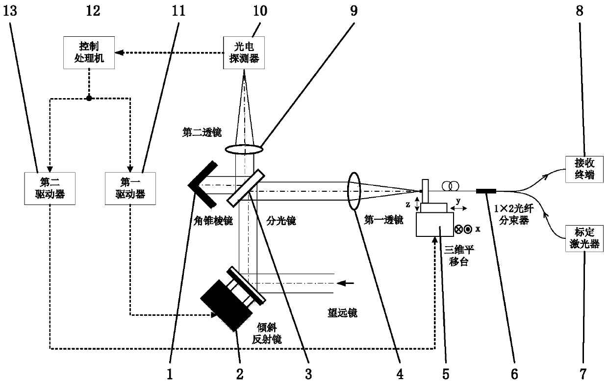
[0013] Such as figure 1 As shown, a spatial light-to-fiber coupling system of the present invention includes a corner cube prism 1, an inclined mirror 2, a beam splitter 3, a first lens 4, a three-dimensional translation stage 5, a 1×2 fiber beam splitter 6, and a calibration laser 7. Receiving terminal 8, photodetector 10, second lens 9, first driver 11, control processor 12 and second driver 13. 1×2 optical fiber beam splitter 6 adopts mode field radius w 0 It is a 4.5μm single-mode polarization-maintaining fiber, and the energy ratio of the two beams after splitting is 1:99. According to the mode field matching principle between the focusing of the first lens 4 and the mode field of the optical fiber, the effective light aperture of the first lens 4...


PUM


Abstract

The invention discloses a spatial light-to-fiber coupling system. The system comprises a pyramid prism, an inclined reflector, a light splitter, a first lens, a three-dimensional translation table, a1*2 optical fiber beam splitter, a calibration laser device, a receiving terminal, a photoelectric detector, a second lens, a first driver, a control processor and a second driver. The principle thatthe pyramid prism can return incident light in the original direction is used, and the zero point of the fiber axis is calibrated through the calibration laser device and the pyramid prism. After thespace light to be coupled enters the photoelectric detector and a fiber branch, the control processor acquires light spot data of the photoelectric detector and controls the inclined reflector to moveby taking the zero point of the fiber axis as a benchmark, and the optical axis deviation between the spatial light and a fiber is corrected so that the spatial light can be coupled into the fiber. The system is used for correcting light beam jitter and the optical axis deviation caused by atmospheric disturbance, environment vibration, temperature and gravity changes and the like, the coupling efficiency of the spatial light and the fiber is improved, and the system has an important application prospects in the field of spatial laser communication.

Description

technical field [0001] The invention belongs to the field of spatial light and fiber optics, and in particular relates to a spatial light-to-fiber coupling system. Background technique [0002] Space laser communication technology uses laser beams as the carrier to transmit space information. Compared with traditional microwave communication, it has the characteristics of wide frequency range, strong confidentiality, anti-electromagnetic interference, and no need to apply for frequency bands. The space laser carrier usually uses an optical antenna as the receiving terminal, and couples the space light into a single-mode or multi-mode fiber for information transmission and demodulation. Space light to fiber coupling technology is one of the key technologies of space laser communication, but space light is subject to beam jitter and optical axis deviation caused by atmospheric disturbance, environmental vibration, temperature and gravity changes, etc., making it difficult to ...

Claims


Application Information

Patent Timeline
Patent Type & Authority Patents(China)
IPC IPC(8): G02B6/42
CPCG02B6/4204G02B6/4214G02B6/4225
Inventor 芮道满刘超陈莫鲜浩
Owner INST OF OPTICS & ELECTRONICS - CHINESE ACAD OF SCI
Why Eureka
Try Eureka