Method for manufacturing COB light source

A manufacturing method and light source technology, applied in electrical components, electrical solid devices, circuits, etc., can solve the problems of inability to achieve high-density integration, large spacing between LED chips, etc., and achieve high-density integration, simple manufacturing process, and simple structure. Effect

Active Publication Date: 2018-07-27
GUANGDONG RAYTON INTELLIGENT OPTO CO LTD
View PDF4 Cites 3 Cited by
  • Summary
  • Abstract
  • Description
  • Claims
  • Application Information

AI Technical Summary

Problems solved by technology

Due to the large size of CSP, the interval between LED chips is relatively large, and this kind of COB light source cannot achieve high-density integration

Method used


Image

  • Method for manufacturing COB light source
  • Method for manufacturing COB light source
  • Method for manufacturing COB light source

Examples


Embodiment 1

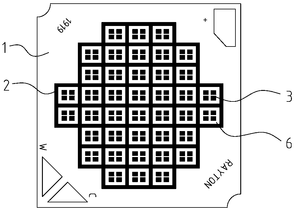
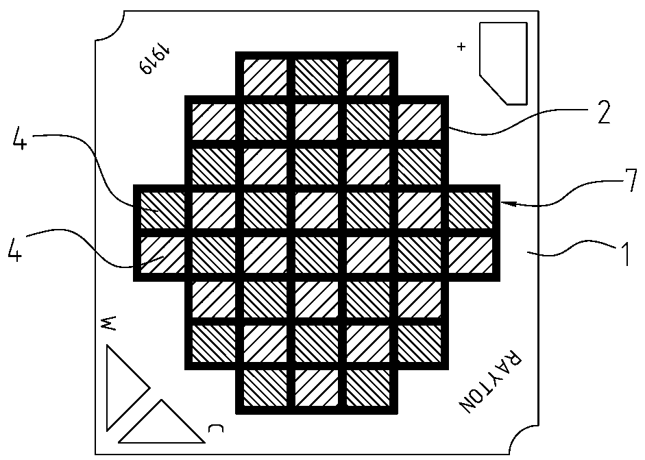
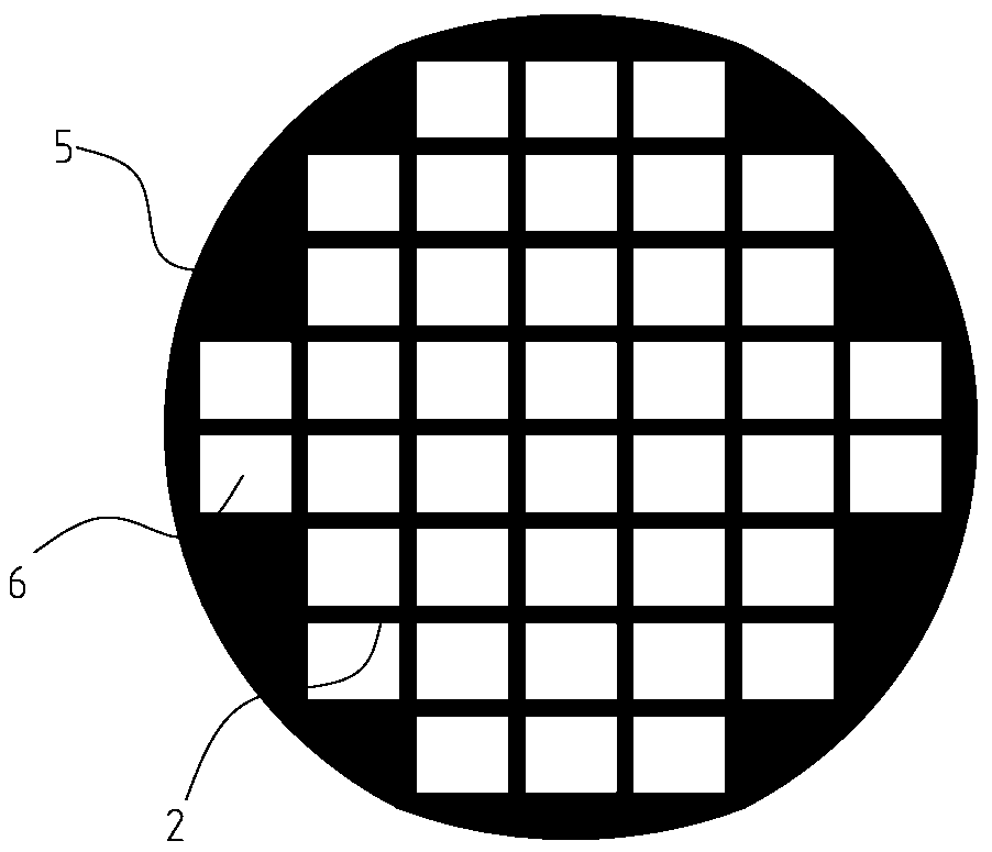
[0044] Such as figure 1 , 2 , 5, a COB light source includes a substrate 1, a number of LED chips 3 distributed on the substrate 1 and a fluorescent film 7 for light distribution. The fluorescent film 7 includes a grid 2, the grid 2 is fixed on the substrate 1, a number of filling regions 6 are formed in the grid 2, and the shape of the grid 2 is the same as that of the crystal-bonding region on the substrate 1 , the filling area 6 is in one-to-one correspondence with the LED chips 3 , that is, each LED chip 3 is located in the filling area 6 . The filling area 6 is provided with a fluorescent glue 4. The fluorescent glue 4 in this embodiment includes a positive white fluorescent glue and a warm white fluorescent glue. The warm white fluorescent glue and the positive white fluorescent glue are distributed at intervals. Thus, white light with different color temperatures is produced.

[0045] The manufacturing method of the COB light source comprises the following steps:

...

Embodiment 2

[0052] Such as Figures 3 to 6 As shown, a COB light source includes a substrate 1, several LED chips 3 distributed on the substrate 1, and a fluorescent film 7 for light distribution. The fluorescent film 7 includes a grid 2, the grid 2 is fixed on the substrate 1, a number of filling regions 6 are formed in the grid 2, and the shape of the grid 2 is the same as that of the crystal-bonding region on the substrate 1 , the filling area 6 is in one-to-one correspondence with the LED chips 3 , that is, each LED chip 3 is located in the filling area 6 . The filling area 6 is provided with a fluorescent glue 4. The fluorescent glue 4 in this embodiment includes a positive white fluorescent glue and a warm white fluorescent glue. The warm white fluorescent glue and the positive white fluorescent glue are distributed at intervals. Thus, white light with different color temperatures is produced.

[0053] The manufacturing method of the COB light source comprises the following steps:...

Embodiment 3

[0061] Such as Figures 3 to 6 As shown, a COB light source includes a substrate 1, several LED chips 3 distributed on the substrate 1, and a fluorescent film 7 for light distribution. The fluorescent film 7 includes a grid 2, the grid 2 is fixed on the substrate 1, a number of filling regions 6 are formed in the grid 2, and the shape of the grid 2 is the same as that of the crystal-bonding region on the substrate 1 , the filling area 6 is in one-to-one correspondence with the LED chips 3 , that is, each LED chip 3 is located in the filling area 6 . The filling area 6 is provided with a fluorescent glue 4. The fluorescent glue 4 in this embodiment includes a positive white fluorescent glue and a warm white fluorescent glue. The warm white fluorescent glue and the positive white fluorescent glue are distributed at intervals. Thus, white light with different color temperatures is produced.

[0062] The manufacturing method of the COB light source comprises the following steps:...


PUM


Abstract

Provided is a method for manufacturing a COB light source. The method comprises the steps that (1), die bonding is conducted on a substrate; (2), a fluorescent film is formed on the substrate; (3) thefluorescent film is fixed on the substrate to form the COB light source; a forming method of the fluorescent film includes the steps of (1), conducting in-mold injection molding to form grids, and dispensing fluorescent glue in filling areas of the grids; (2), conducting injection moulding to form grids, and dispensing fluorescent glue in filling areas of the grids; (3), conducting aluminum sheetpunch forming to form grids, and dispensing fluorescent glue in filling areas of the grids. The method has the advantages of simple structure and simple manufacturing process, all chips are blue light chips, and the chips are firstly die-bonded on the substrate to achieve high-density integration of the LED chips.

Description

technical field [0001] The invention relates to the field of LEDs, in particular to a method for manufacturing a two-color temperature COB light source. Background technique [0002] COB light source is a high-efficiency integrated surface light source that pastes LED chips directly on a mirror substrate with high reflectivity, adopts COB packaging technology to bond with the circuit board through bonding wires, and covers it with resin to ensure reliability. LED light sources with other structures have the advantages of stable electrical properties, high color rendering, uniform light emission, fast heat dissipation, easy light distribution, no reflow soldering, and reduced difficulty in lamp design, so they are more and more widely used in the field of LED packaging technology . [0003] At present, in the existing COB light source lamps, the display of high or low color temperature of COB is controlled by different types of phosphors and the proportion of phosphors confi...

Claims


Application Information

Patent Timeline
Patent Type & Authority Applications(China)
IPC IPC(8): H01L25/075H01L33/50
CPCH01L25/0753H01L33/504H01L33/508H01L2933/0041
Inventor 陈焕杰李金龙吴江辉
Owner GUANGDONG RAYTON INTELLIGENT OPTO CO LTD
Why Eureka
Try Eureka