
Smart home system and smart socket

A smart socket and socket technology, applied in the direction of electrical components, coupling devices, circuits, etc., can solve the problem of limited use area of ​​voice control system, and achieve the effect of solving the limited use area

Pending Publication Date: 2018-07-27
ZHENGZHOU SENYUAN NEW ENERGY TECH
View PDF0 Cites 2 Cited by
  • Summary
  • Abstract
  • Description
  • Claims
  • Application Information

AI Technical Summary

Problems solved by technology

[0004] The purpose of the present invention is to provide a smart socket to solve the problem of limited use area of ​​the voice control system of the smart home in the prior art; in addition, the purpose of the present invention is to provide a smart home system using the smart socket

Method used


Image

  • Smart home system and smart socket
  • Smart home system and smart socket
  • Smart home system and smart socket

Examples


specific Embodiment 2

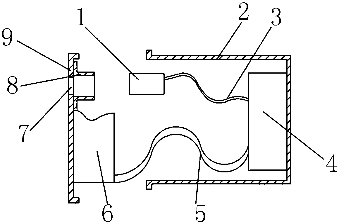
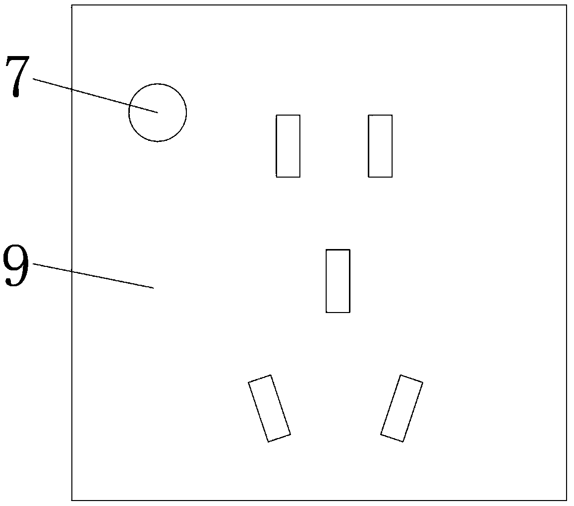
[0038]Specific embodiment 2 of the smart home system of the present invention, the smart home system includes a control terminal for controlling smart home devices and a smart socket, the smart socket includes a socket base and a socket panel fixed on the socket base, the smart socket It also includes a voice receiving module for receiving voice and a signal transmitting module connected with the voice receiving module and used for signal connection with the control terminal to send the voice signal received by the voice receiving module to the control terminal. Because in the room, the socket is distributed throughout the room and is an indispensable part. By setting the voice receiving module and the signal connector connected with the voice receiving module on the smart socket, the voice receiving module will be received through the control interface on the signal connector. The voice signal received by the module is transmitted to the control terminal, and the control termi...

specific Embodiment 5

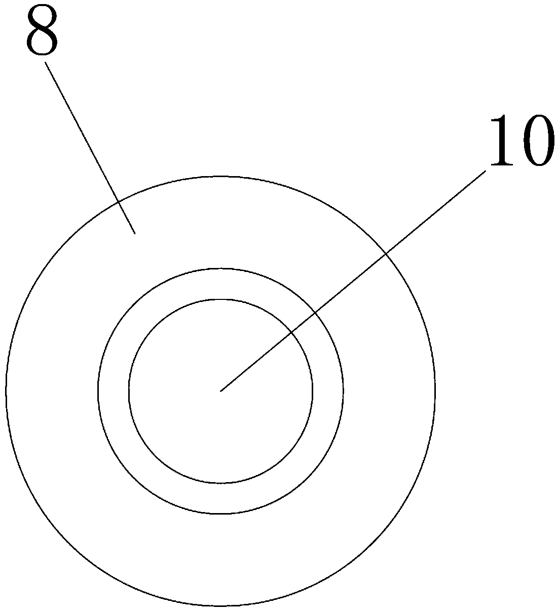
[0041] The specific embodiment 5 of the smart home system of the present invention, as a further optimization of the specific embodiment 4 of the smart home system of the present invention, the microphone is cylindrical, the fixed structure is a sleeve, and the center of the sleeve is provided with a microphone The sleeve is provided with a sleeve fixing surface for fixing the sleeve on the socket panel. When installing the microphone, you only need to insert the microphone into the through hole of the sleeve, which is more convenient for installation. Of course, in other embodiments, the fixing structure may also use conventional screw fixing or bonding to fix the voice receiver.

specific Embodiment 6

[0042] The specific embodiment 6 of the smart home system of the present invention, as a further optimization of the specific embodiment 5 of the smart home system of the present invention, the sleeve fixing surface is used to be fixed on the side of the socket panel facing the socket base, which is convenient for the socket The panel is flat and beautiful. Of course, in other embodiments, the sleeve can also be fixed on the plane of the socket panel facing the outside of the smart socket, or on the socket base.


PUM


Abstract

The invention provides a smart home system and a smart socket, which is within the technical field of smart home equipment. The smart socket includes a socket base and a socket panel fixed to the socket base. The smart socket further includes a voice receiving module for receiving voice and a signal connection with the voice receiving module, and for connecting to the control terminal signal to transmit the voice signal received by the voice receiving module to the signal transmitting module of the control terminal. When the user performs voice commands or performs voice interaction on the smart home in any area of the room, the voice information of the user is transmitted to the control terminal through the signal transmitting module through the voice receiving module distributed in the socket on each area of the room. Furthermore, by controlling the terminal to control other smart home devices, the problem of the limited use area of the voice control system in the prior art is solved.

Description

technical field [0001] The invention relates to the field of smart home, in particular to a smart home system and a smart socket thereof. Background technique [0002] Smart home refers to a residential facility and family schedule management system that uses the residence as a platform and uses integrated wiring technology, network communication technology, security technology, automatic control technology, audio and video technology, etc. . Compared with ordinary homes, smart homes not only have traditional living functions, but also have functions such as network communication, information appliances, and equipment automation, which can provide all-round information interaction. [0003] Most of the existing smart homes use voice control for human-computer interaction. The mainstream voice control systems on the market mainly rely on major smart speaker manufacturers. This kind of radio effect is extremely unsatisfactory and must be within the range of smart speakers. P...

Claims


Application Information

Patent Timeline
Patent Type & Authority Applications(China)
IPC IPC(8): H01R13/66H01R13/502
CPCH01R13/502H01R13/66H01R13/6691
Inventor 赵荣尚宋浩马娜何帅
Owner ZHENGZHOU SENYUAN NEW ENERGY TECH
Learn More