
Cover plate, storage device with cover plate and kitchen equipment applying cover plate

A technology of kitchen equipment and cover plate, which is applied in the field of kitchen utensils, can solve the problems of inconvenient cleaning of the countertop, dust, debris falling under the countertop, etc., and achieve the effect of improving neatness and aesthetics, good sealing, and neat and beautiful appearance

Pending Publication Date: 2021-03-30
NINGBO FOTILE KITCHEN WARE CO LTD
View PDF3 Cites 0 Cited by
  • Summary
  • Abstract
  • Description
  • Claims
  • Application Information

AI Technical Summary

Problems solved by technology

Furthermore, parts such as faucets are usually arranged on the table, and the cover easily interferes with the parts (such as the faucet) on the table when it is opened.
[0004] In addition, in order to make full use of the space under the countertop, some items, such as grain, oil, etc., will be placed under the countertop, and then a through hole will be opened on the countertop to pick and place items from the through hole, but the setting of the through hole will make dust , debris, etc. fall into the bottom of the table from here, and the bottom of the table is not easy to clean

Method used


Image

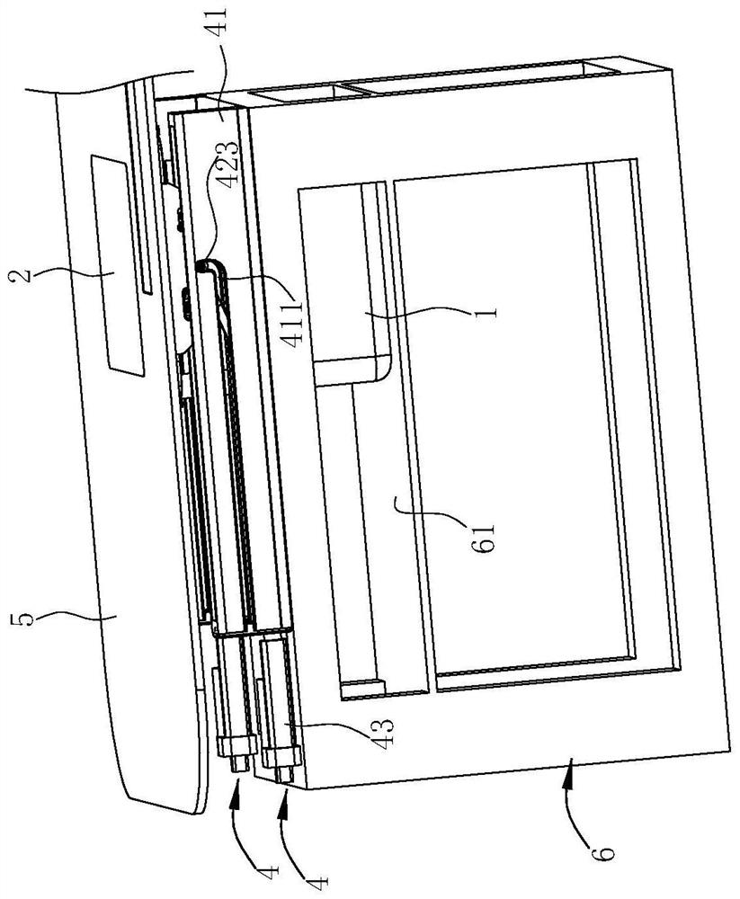
  • Cover plate, storage device with cover plate and kitchen equipment applying cover plate
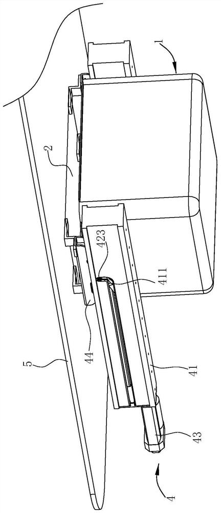
  • Cover plate, storage device with cover plate and kitchen equipment applying cover plate
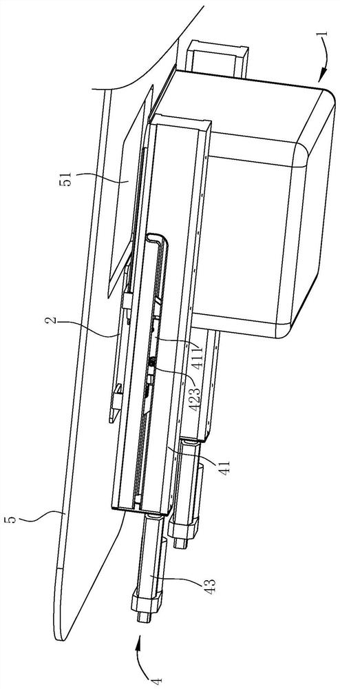
  • Cover plate, storage device with cover plate and kitchen equipment applying cover plate

Examples


Embodiment 2

[0056] The difference between Embodiment 2 and Embodiment 1 is that: a first sealing ring 21 is provided on the cover body 2 .

[0057] Such as Figure 8 As shown, the periphery of the cover body 2 is formed with a circle of downwardly extending steps 22, and the step surface 221 of the steps 22 is provided with a first sealing ring 21. When the cover body 2 is embedded in the through hole 51, The first sealing ring 21 abuts against the lower end surface of the table top 5 and surrounds the outer periphery of the through hole 51 to prevent water, oil, etc. 2 and the gap between the platform 5 drops into the first accommodating tank 1 .

[0058] In addition, the step 22 can also play a positioning role. For example, for the sake of appearance, when the cover body 2 is moved into the through hole 51, the upper end surface of the cover body 2 is flush with the upper end surface of the table 5, so the step is designed. The height of 22 can play the role of limiting the moving st...

Embodiment 3

[0060] Such as Figure 9 , 10 As shown, the difference between embodiment 3 and embodiment 2 is that the first accommodation groove 1 is not provided, and at this time the cover body 2 can still be embedded in the through hole 51 under the action of the drive assembly 4 (see Figure 9 ), or the cover plate body 2 is located below the table top 5 and at least partially deviates from the direct position of the through hole 51 (see Figure 10 ). This embodiment is more suitable for the following scenarios: in order to make full use of the space below the table top 5, some items, such as grain, oil, etc., will be placed under the table top 5, and the items will be picked and placed from the through hole 51 of the table top 5, but the through hole 51 will make Dust, debris, etc. fall into the bottom of the table top 5 from here, and the bottom of the table top 5 is not easy to clean, so a cover plate is set to solve this problem. Objects fall from the through hole 51 below the t...

Embodiment 4

[0062] Embodiment 4 is to protect a storage device with a cover plate without a table top 5. The storage device includes a second accommodating tank 7 with an open top. The structure of the cover plate is except for the arrangement of the second guide section and the sealing ring. Different, other structures of the cover plate can refer to embodiment 2, specifically as follows:

[0063] Such as Figures 11 to 14 As shown, the top of the second accommodating groove 7 is open, and the cover body 2 can close the notch of the second accommodating groove 7 or at least partially deviate from the position facing the notch of the second accommodating groove 7 . The slide rail 3 is located on one side of the second receiving slot 7 and extends along the horizontal direction, and the driving assembly 4 is used to drive the cover body 2 to translate or lift relative to the second receiving slot 7 .

[0064] Such as Figure 12 , 13 As shown, the driving assembly 4 includes a guide fram...


PUM


Abstract

The invention relates to a cover plate, a storage device with the cover plate and kitchen equipment applying the cover plate, and the cover plate comprises a sliding rail which extends in the horizontal direction; a cover plate body which is positioned on one side of the slide rail and can translate relative to the slide rail; a driving assembly which comprises a guide frame, a guide groove is formed in the guide frame, and the guide groove comprises a first guide section parallel to the sliding rail; a lifting frame which comprises a first supporting rod and a second supporting rod which arearranged in a crossed mode and hinged through a pin shaft at the crossed position, the lower portion of the first supporting rod and the lower portion of the second supporting rod are both arranged onthe sliding rail in a sliding mode, the upper portion of the first supporting rod and the upper portion of the second supporting rod are both connected with the cover plate body in a sliding mode, and the pin shaft is arranged in the guide groove; and a driving piece which is in driving connection with the first supporting rod or the second supporting rod and used for driving the lifting frame tomove along the sliding rail. Due to the driving mode of the cover plate, the cover plate body does not occupy the space above a covered part when being opened.

Description

technical field [0001] The invention relates to kitchen utensils, in particular to a cover, a storage device with the cover and kitchen equipment using the cover. Background technique [0002] Some embedded devices in modern kitchens, such as sinks, storage boxes, cooking tanks, trash cans, etc., are usually placed under the countertop, and as people pay more and more attention to the quality of life, these embedded devices are usually equipped with a cover Board, in order to play a dust-proof effect, such as the trash can embedded under the table, the garbage on the table can be directly swept into the trash can, and for example the patent No. ZL201821229012. A stainless steel cabinet with a built-in storage box" shows that the cover plate and the built-in groove are rotatably connected by a rotating shaft. This method has the problem of occupying space on the table when the cover plate is in an open state. [0003] Or as described in the "Sink Dishwasher with Steam Box" d...

Claims


Application Information

Patent Timeline
Patent Type & Authority Applications(China)
IPC IPC(8): A47J47/00A47J36/06E03C1/186
CPCA47J36/06A47J47/00E03C1/186
Inventor 韩海波王蒙张金京
Owner NINGBO FOTILE KITCHEN WARE CO LTD
Learn More