Optical link terminal bearing capability testing method, optical link terminal bearing capability testing device, and optical link terminal bearing capability testing system

A technology of optical line terminal and carrying capacity, which is applied in the field of passive optical network and Ethernet, and can solve the problems of huge test cost consumption and difficult realization of OLT carrying capacity test, etc.

Inactive Publication Date: 2018-07-27
LUSTER TERABAND PHOTONICS TECHNOLOGY CO LTD
View PDF6 Cites 4 Cited by
  • Summary
  • Abstract
  • Description
  • Claims
  • Application Information

AI Technical Summary

Problems solved by technology

[0004] At present, in order to test the carrying capacity of the OLT, it is necessary to build a large number of ONUs as terminals for performance simulation testing. Loading 4096 ONUs can simulate the largest topology of the existing network, which requires a large number of ONUs and sites, resulting in a huge cost of OLT carrying capacity testing, and requires a large area of ​​testing sites, making OLT carrying capacity testing difficult to achieve

Method used


Image

  • Optical link terminal bearing capability testing method, optical link terminal bearing capability testing device, and optical link terminal bearing capability testing system
  • Optical link terminal bearing capability testing method, optical link terminal bearing capability testing device, and optical link terminal bearing capability testing system
  • Optical link terminal bearing capability testing method, optical link terminal bearing capability testing device, and optical link terminal bearing capability testing system

Examples


Embodiment Construction

[0056] The following will clearly and completely describe the technical solutions in the embodiments of the present invention with reference to the accompanying drawings in the embodiments of the present invention. Obviously, the described embodiments are part of the embodiments of the present invention, not all of them. Based on the embodiments of the present invention, all other embodiments obtained by persons of ordinary skill in the art without creative efforts fall within the protection scope of the present invention.

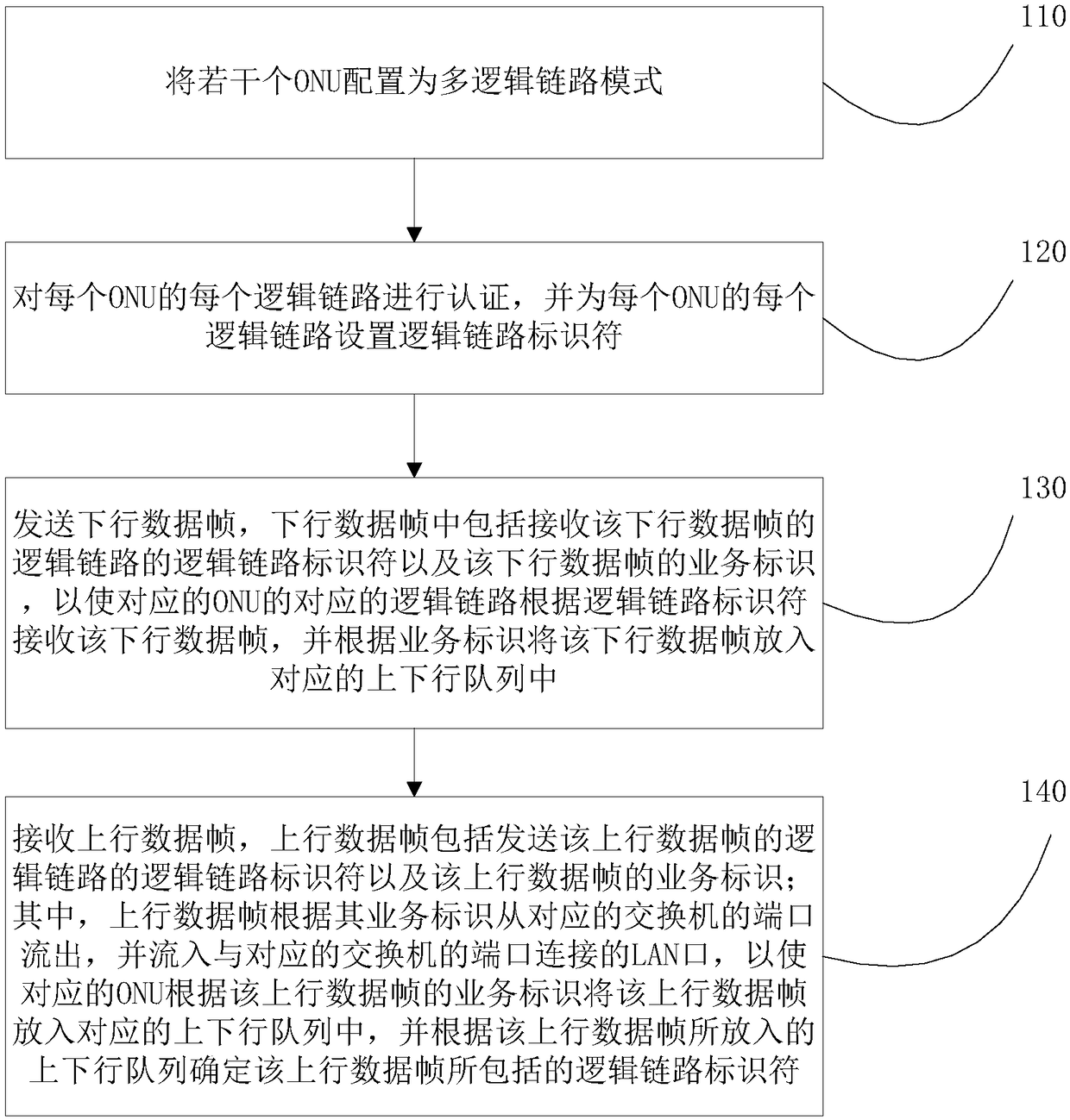
[0057] A method for testing the carrying capacity of an optical line terminal, such as figure 1 As shown, the method includes the following steps:

[0058] 110. Configure several ONUs in multi-logical link mode, wherein the ONU in multi-logical link mode has multiple logical links, and each logical link corresponds to several upstream and downstream queues, and each upstream and downstream queue uses Uplink data frames and / or downlink data frames of a pr...


PUM


Abstract

The invention provides an optical link terminal bearing capability testing method, an optical link terminal bearing capability testing device, and an optical link terminal bearing capability testing system. An optical network unit (ONU) is configured in a mode of a plurality of logical links, and each logical link is provided with a logical link identifier and an uplink-downlink queue, and each uplink-downlink queue is provided with a business type. An optical line terminal (OLT) is used to transmit a downlink data frame, and the corresponding logical link is used to receive the downlink dataframe, and according to the business identifier, the downlink data frame is disposed in the corresponding uplink-downlink queue. An uplink data frame is output through a port of a corresponding switchaccording to the business identifier, and the corresponding ONU is used to arrange the uplink data frame in the corresponding uplink-downlink queue according to the business identifier of the uplinkdata frame, and then the logical link identifier included by the uplink data frame is determined, and the OLT is used to receive the uplink data frame. According to the abovementioned technical scheme, each ONU is used to simulate a plurality of ONUs by adopting the design of a plurality of logical links, and therefore the number of the ONUs required in an OLT bearing capability test and an area occupied by the test are effectively reduced.

Description

technical field [0001] Embodiments of the present invention relate to the technical fields of passive optical network and Ethernet, and more specifically, relate to a method, device and system for testing the carrying capacity of an optical line terminal. Background technique [0002] EPON (Ethernet Passive Optical Network, Ethernet Passive Optical Network) is an Ethernet-based passive optical network technology. It adopts a point-to-multipoint structure, uses passive optical fiber for data transmission, provides users with various business services on Ethernet, and combines the advantages of PON (passive optical network) technology and Ethernet technology. like Figure 11 As shown, the EPON system is composed of a central office equipment OLT (Optical Line Terminal, Optical Line Terminal), a user equipment ONU (Optical Network Unit, Optical Network Unit) and an Optical Distribution Network (ODN, Optical Distribution Network). The OLT is used to connect the main optical fib...

Claims


Application Information

Patent Timeline
Patent Type & Authority Applications(China)
IPC IPC(8): H04Q11/00H04B10/077H04B10/079H04L12/24H04L12/26
CPCH04B10/0773H04B10/0775H04B10/0795H04L41/145H04L43/0817H04Q11/0067H04Q2011/0083H04Q2011/0084
Inventor 柳旺姚毅庹磊刘曾霖
Owner LUSTER TERABAND PHOTONICS TECHNOLOGY CO LTD
Why Eureka
Try Eureka