Screw-type injection molding machine for injection molding

An injection molding and injection molding machine technology, which is applied in the field of mold injection molding, can solve the problems of no fine crushing, influence of melting effect, fixed screw advancing area and driving force, etc., so as to improve the injection molding effect, ensure the fine crushing effect, and avoid failures. Effect

Pending Publication Date: 2018-07-31
黄子奇
View PDF4 Cites 3 Cited by
  • Summary
  • Abstract
  • Description
  • Claims
  • Application Information

AI Technical Summary

Problems solved by technology

[0003] The object of the present invention is to provide a kind of injection molding machine for screw-type injection molding, to solve the problem that in the actual work of the existing screw-type injection molding machine proposed in the above-mentioned background technology, the pushing area and pushing force of the screw are fixed. The propulsion effect of the plastic solution cannot be further improved, and there are limitations in the feeding process. The plastic is not finely crushed before entering the injection molding machine, and it is easy to affect the melting effect.

Method used


Image

  • Screw-type injection molding machine for injection molding
  • Screw-type injection molding machine for injection molding
  • Screw-type injection molding machine for injection molding

Examples


Embodiment Construction

[0018] The following will clearly and completely describe the technical solutions in the embodiments of the present invention with reference to the accompanying drawings in the embodiments of the present invention. Obviously, the described embodiments are only some, not all, embodiments of the present invention. Based on the embodiments of the present invention, all other embodiments obtained by persons of ordinary skill in the art without making creative efforts belong to the protection scope of the present invention.

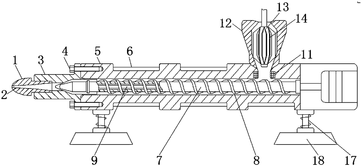
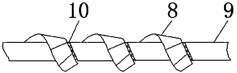
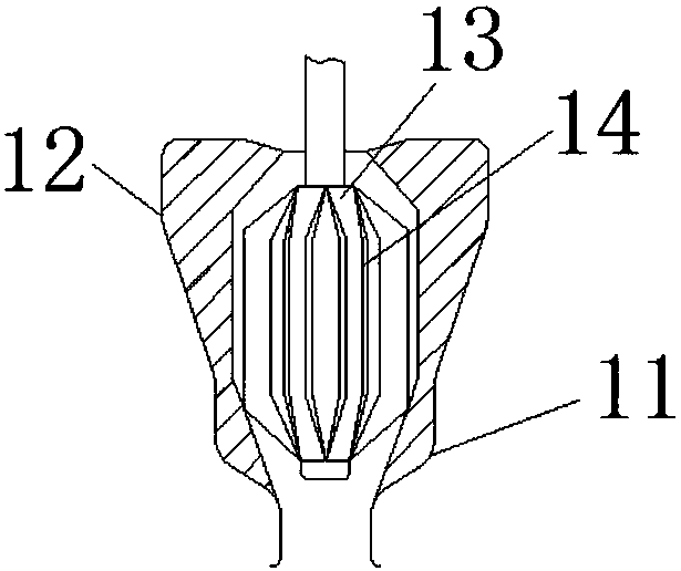
[0019] see Figure 1-4 , the present invention provides a technical solution: a screw type injection molding machine, comprising a nozzle 1, a screw 7 and a scrap head 13, the nozzle 1 is provided with an injection flow channel 2, and the right side of the nozzle 1 is installed with The nozzle flange 3, the upper and lower sides of the nozzle flange 3 are provided with hexagon socket head screws 4, and the right side of the nozzle flange 3 is equipped with a b...


PUM


Abstract

The invention discloses a screw-type injection molding machine for injection molding. The screw-type injection molding machine comprises a nozzle, a screw and a material crushing head. An injection molding flow pass is formed in the nozzle, and a nozzle flange is mounted on the right side of the nozzle. Inner hexagon screws are arranged on the upper side and the lower side of the nozzle flange correspondingly, and a charging barrel is mounted on the right side of the nozzle flange. A heat transfer metal ring is fixed to the outer wall of the charging barrel, and screw teeth are arranged on theouter wall of the screw. The screw is located in the middle of the charging barrel, and a control rod is arranged in the middle of the screw. Balls are inlaid in the outer wall of the control rod, and an electric heating wire sleeve is mounted on the upper portion of the right side of the screw. A material opening is formed in the upper portion of the electric heating wire sleeve, and a fine crushing knife is mounted on the outer side of the material crushing head. The material crushing head is located in the middle of the material opening. According to the screw-type injection molding machine for injection molding, the propulsion area of the screw can be adjusted, the propulsion angle of molten plastic by the screw can be adjusted, and the plastic can be finely crushed in advance.

Description

technical field [0001] The invention relates to the technical field of mold injection molding, in particular to an injection molding machine for screw type injection molding. Background technique [0002] The screw is an important part of the injection molding machine. Its function is to convey, compact, melt, stir and press the plastic, all of which are completed by the rotation of the screw in the barrel. When the screw rotates, the plastic is There will be friction and mutual motion between the inner wall of the barrel, the bottom surface of the screw groove, the propulsion surface of the screw edge, and the plastic and plastic. However, when the existing screw type injection molding machine is actually working, the advancing area and advancing force of the screw are fixed, and the advancing effect of the plastic solution cannot be improved, and there are limitations in the feeding process. When entering the injection molding machine, although it will be heated evenly un...

Claims


Application Information

Patent Timeline
Patent Type & Authority Applications(China)
IPC IPC(8): B29C45/03B29C45/17B29C45/47B29C45/74B29B13/10
CPCB29B13/10B29C45/03B29C45/17B29C45/1761B29C45/47B29C45/74B29C2045/1765
Inventor 卓苏旭裴亚亚吕晶森刘森金赛珍
Owner 黄子奇
Why Eureka
Try Eureka