Power device

A technology for power devices and electrical equipment, applied in the direction of coupling devices, parts and circuits of connecting devices, etc., can solve problems such as hidden safety hazards of power supply sockets, influence of electrical equipment, and plugs falling off.

Inactive Publication Date: 2018-07-31
吴丽清
View PDF5 Cites 2 Cited by
  • Summary
  • Abstract
  • Description
  • Claims
  • Application Information

AI Technical Summary

Problems solved by technology

[0002] With the improvement of the application level of electric power technology, there are more and more types of electrical equipment, which brings great convenience to people. These electrical equipment need to be energized before they can operate. Traditional electrical equipment uses conductive rods. Insert it into the slot to complete the power supply, but because the slots are generally directly connected to the outside, and the power supply piece extends into the slot, and the power supply piece is directly connected to the mains, therefore, ordinary metal rods are inserted into the The slot will be in contact with the power supply sheet, which will cause an electric shock accident. Therefore, the traditional power supply stand has great potential safety hazards. When the traditional plug is matched with the power supply stand, if you accidentally kick the plug or kick the wire , it will cause the plug to fall off, which will cause a sudden power failure of the electrical equipment, which will easily affect the electrical equipment

Method used


Image

  • Power device
  • Power device

Examples


Embodiment Construction

[0017] All features disclosed in this specification, or steps in all methods or processes disclosed, may be combined in any manner, except for mutually exclusive features and / or steps.

[0018] Any feature disclosed in this specification, unless specifically stated, can be replaced by other alternative features that are equivalent or have similar purposes. That is, unless expressly stated otherwise, each feature is one example only of a series of equivalent or similar features.

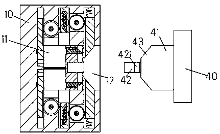
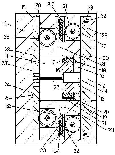
[0019] Such as figure 1 with figure 2 As shown, a power device of the device of the present invention includes a socket 10 and a plug 40 connected to electrical equipment. The socket 10 is provided with a sliding cavity 11 extending laterally, and the inner wall of the sliding cavity 11 is provided on the right side. There is a slot 12 connected to the outside, and the upper and lower end walls of the sliding chamber 11 are symmetrically arranged with a first sliding groove 19, a second sliding gro...


PUM


Abstract

The invention discloses a power device which comprises a socket and a plug connected with an electric device, a sliding cavity which extends transversely is arranged in the socket, an inserting groovecommunicated with the outside is formed in the inner wall of the right side of the sliding cavity, a first sliding groove, a second sliding groove and a third sliding groove that are sequentially, vertically and symmetrically formed in the upper end wall and the lower end wall of the sliding cavity from left to right, the first sliding groove, the second sliding groove and the third sliding groove are communicated with the sliding cavity, a first sliding plate is arranged in the first sliding groove in a sliding mode, a first rack is arranged on the right end surface of the first sliding plate, a second sliding plate is arranged in the second sliding groove in a sliding mode, second racks are symmetrically arranged on the end surfaces of the two sides of the second sliding plate, a thirdsliding plate is arranged in the third sliding groove in a sliding mode, the left end face of the third sliding plate is provided with a third rack, and a first inclined head extending into the inserting groove is arranged at the bottom of the third sliding plate.

Description

technical field [0001] The invention relates to an electric device. Background technique [0002] With the improvement of the application level of electric power technology, there are more and more types of electrical equipment, which brings great convenience to people. These electrical equipment need to be energized before they can operate. Traditional electrical equipment uses conductive rods. Insert it into the slot to complete the power supply, but because the slots are generally directly connected to the outside, and the power supply piece extends into the slot, and the power supply piece is directly connected to the mains, therefore, ordinary metal rods are inserted into the The slot will be in contact with the power supply sheet, which will cause an electric shock accident. Therefore, the traditional power supply stand has great potential safety hazards. When the traditional plug is matched with the power supply stand, if you accidentally kick the plug or kick the w...

Claims


Application Information

Patent Timeline
IPC IPC(8): H01R13/639H01R13/70
CPCH01R13/639H01R13/701
Inventor 覃嘉查王程吴小茹
Owner 吴丽清
Why Eureka
Try Eureka