
Microelectromechanical microphone

A microphone and micro-electromechanical technology, applied in the field of micro-electro-mechanical microphones, can solve the relative positioning of difficult micro-electro-mechanical microphone components and other problems

Inactive Publication Date: 2018-07-31
INFINEON TECH AG
View PDF8 Cites 3 Cited by
  • Summary
  • Abstract
  • Description
  • Claims
  • Application Information

AI Technical Summary

Problems solved by technology

The essential problem in this case is the mechanical or thermal stress to which the microphone components are subjected and which can lead to deformations of these components, which in turn makes it difficult to carry out micro-electromechanical microphone components. well-defined relative positioning

Method used


Image

  • Microelectromechanical microphone
  • Microelectromechanical microphone
  • Microelectromechanical microphone

Examples


Embodiment Construction

[0012] The detailed description hereinafter refers to the accompanying drawings that, for purposes of illustration, show specific details and implementations in which various embodiments can be practiced.

[0013] The concept "exemplary" is used herein to mean "serving as an example, as an illustration, or for illustration." Each implementation or configuration described herein as "exemplary" is not necessarily to be construed as preferred or advantageous over other implementations or configurations.

[0014] In the drawings, the same reference numerals refer to the same parts in different views. The drawings serve primarily to illustrate principles of the various embodiments and are therefore not necessarily to scale.

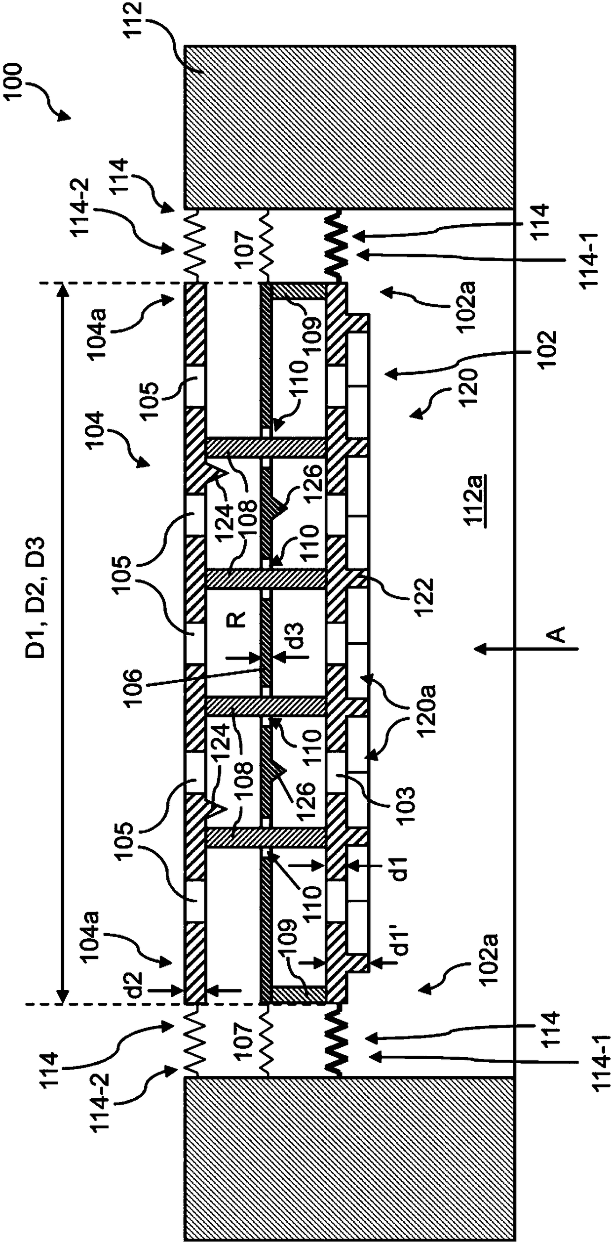
[0015] exist figure 1 An exemplary microelectromechanical microphone 100 is shown in . The MEMS microphone 100 has a flat first electrode 102 and a flat second electrode 104 , and the second electrode is spaced apart from the first electrode 102 .

[0016]...


PUM


Abstract

A microelectromechanical microphone includes a planar first electrode that is formed, at least in portions, from an electrically conductive material, a planar second electrode that is formed, at leastin portions, from an electrically conductive material and that is arranged at a distance from the first electrode, a spacer that is arranged between the first electrode and the second electrode, anda membrane that is arranged in a space defined between the first electrode and the second electrode and that is displaceable in the direction of at least one of the first electrode or the second electrode. The membrane has a membrane passage opening through which the spacer extends. The space defined between the first and the second electrode, in which the membrane is arranged, has a gas exchangeconnection with the surroundings of the microphone.

Description

technical field [0001] Various embodiments relate generally to microelectromechanical microphones. Background technique [0002] MEMS microphones have become very important in modern communications. A major challenge in the manufacture of microelectromechanical microphones is to produce components with a well-defined shape that are arranged relative to each other in a well-defined manner. The essential problem in this case is the mechanical or thermal stress to which the microphone components are subjected and which can lead to deformations of these components, which in turn makes it difficult to carry out micro-electromechanical microphone components. Well-defined relative positioning. [0003] Such stresses may have inherent causes and may be due to thermal as well as mechanical loads during the manufacturing process. Alternatively or additionally, such stresses can be produced only by the coupling of different components, for example by the coupling of a plurality of c...

Claims


Application Information

Patent Timeline
IPC IPC(8): H04R19/04
CPCH04R19/04B81B3/007B81B2201/0257B81B2203/0127B81B2203/04H04R7/20H04R7/24H04R19/005B81B3/0021H04R7/12H04R7/18H04R2201/003
Inventor A·德厄
Owner INFINEON TECH AG
Learn More