
Method for adjusting brake pressures of a vehicle, and brake system for carrying out the method

A brake pressure and pressure control technology, which is applied in road vehicle drive control systems, brakes, brake components, etc., can solve problems such as reduced braking safety and driving comfort, bumps, and difficulty in adjusting brake pressure during deceleration , to achieve the effect of preventive and active intervention

Active Publication Date: 2018-07-31
ZF CV SYST EURO BV
View PDF12 Cites 3 Cited by
  • Summary
  • Abstract
  • Description
  • Claims
  • Application Information

AI Technical Summary

Problems solved by technology

The control of the brake pressure via the ABS during an external brake request can in principle lead to disadvantages
Adapting the brake pressure to the requested vehicle deceleration becomes difficult and especially reduces braking safety and driving comfort
In particular due to a sudden increase in brake pressure, an undesired jerk always occurs again

Method used


Image

  • Method for adjusting brake pressures of a vehicle, and brake system for carrying out the method
  • Method for adjusting brake pressures of a vehicle, and brake system for carrying out the method
  • Method for adjusting brake pressures of a vehicle, and brake system for carrying out the method

Examples


Embodiment Construction

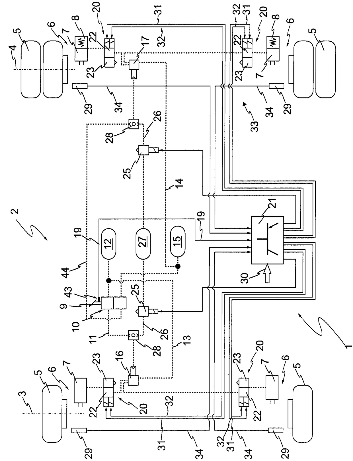
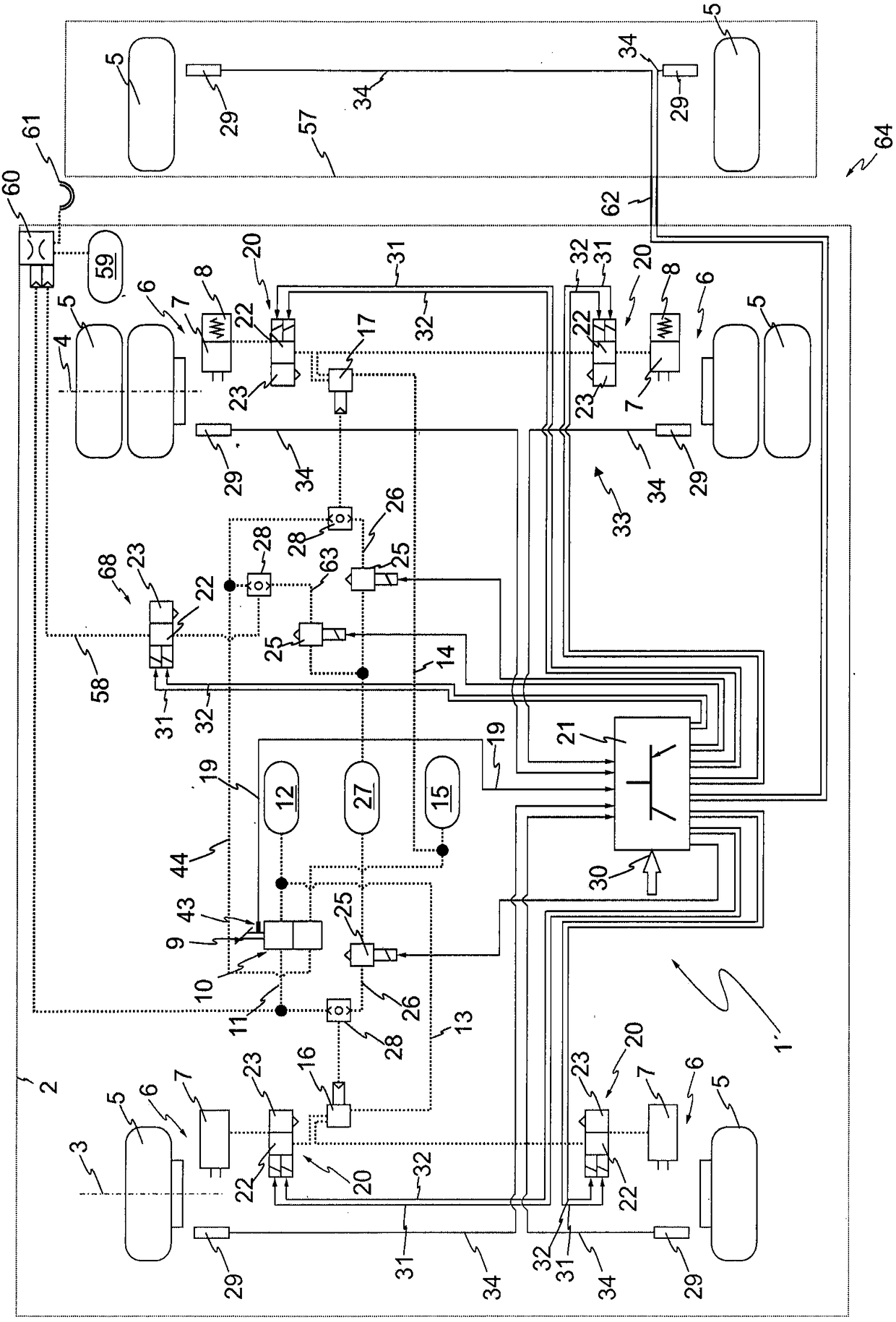
[0054] figure 1 An electrical-pneumatic diagram of a brake system 1 of a vehicle 2 , ie a commercial vehicle, is shown. Electrical lines are shown in solid lines and pneumatic lines are shown in dashed lines. In the exemplary embodiment shown, the vehicle 2 comprises two axles, namely a front axle 3 and a rear axle 4 , on which wheels 5 are arranged on both sides. To brake the wheels 5 , a wheel brake 6 is assigned to each wheel 5 . The wheel brakes 6 are pneumatically actuatable and each have a brake cylinder 7 . The wheel brakes 6 apply a braking force to the rotating wheels 5 depending on the respective pneumatic brake pressure present in the brake cylinders 7 . In this case, brake cylinders 7 with spring accumulators 8 are arranged on the wheels 5 of the rear axle 4 for the parking brake.

[0055] A brake pedal 9 , which is coupled to a service brake valve 10 , is arranged in the cockpit of the vehicle 2 . By actuating the brake pedal 9 , the driver of the vehicle 2 c...


PUM


Abstract

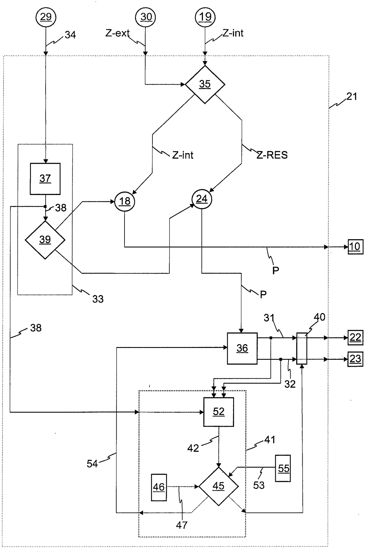
The invention relates to a method for adjusting brake pressures (P) at pneumatically operated wheel brakes of a vehicle, the brake pressure at the wheel brakes being adjusted in a normal braking mode(18) depending on a driver brake request (19). When an external brake request (30) independent of the driver brake request (19) is received, and / or when particular wheels tend to lock, the brake control unit (21) takes over the adjustment of the brake pressure (P) in a pressure control mode (24). In order to ensure a smooth and constant braking behavior of the vehicle (2) when the brake pressure is adjusted in a pressure control mode (24) upon an external brake request (30), the brake control unit (21) continuously determines, in the pressure control mode (24), from measurement signals (34) supplied by wheel (5) speed sensors (29), at least one differential slip value (42) as the difference between the slip (38) of two axles (3, 4) of the vehicle (2) before releasing the control signals for the relevant pressure control valves (20). According to the evaluation, at least one control signal (31, 32) is adapted in order to bring the differential slip value (42) closer to the set differential slip value (53).

Description

technical field [0001] The invention relates to a method for adjusting the brake pressure at pneumatically actuated wheel brakes of a vehicle according to the preamble of claim 1 . Furthermore, the invention relates to a braking arrangement of a vehicle according to the preamble of claim 19 and a vehicle with such a braking arrangement according to claim 25 . Background technique [0002] To brake the motor vehicle, the wheels of the motor vehicle are braked. In commercial vehicles in particular, the wheel brakes of the wheels each have a brake cylinder, wherein the desired brake pressure in the brake cylinder is usually generated pneumatically. [0003] In the normal braking mode, the brake pressure is set according to the driver's braking request determined by the driver of the motor vehicle. Typically, the driver of the motor vehicle communicates his driver braking request by actuating the brake pedal. In known braking systems, a service brake valve is often actuated b...

Claims


Application Information

Patent Timeline
Patent Type & Authority Applications(China)
IPC IPC(8): B60T8/1761B60T8/172
CPCB60T8/172B60T8/1766B60T13/662B60T13/683B60T15/043B60T8/17616B60T8/1708B60T8/327B60Y2400/81B60Y2300/28B60Y2200/148B60T7/12B60T8/1701B60T8/171B60T8/321B60T2240/00B60T2250/00B60T2270/10
Inventor 霍斯特·埃克特
Owner ZF CV SYST EURO BV
Learn More