Guide assembly for sliding doors and cupboard unit
A technology for guiding components and sliding doors, used in door/window fittings, wing parts, power control mechanisms, etc., which can solve problems such as complex assembly and alignment of sliding doors
- Summary
- Abstract
- Description
- Claims
- Application Information
AI Technical Summary
Problems solved by technology
Method used
Image

Examples
Embodiment Construction
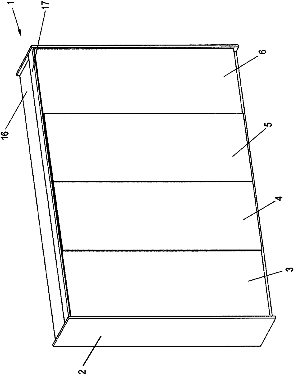
[0037] The cabinet unit 1 comprises a furniture body 2 on its front side provided with sliding doors 3 , 4 , 5 and 6 which cover a top panel 16 of the furniture body 2 at the front. Also mounted on the top plate 16 is a cover 17 which has a shorter depth than the top plate 16 .
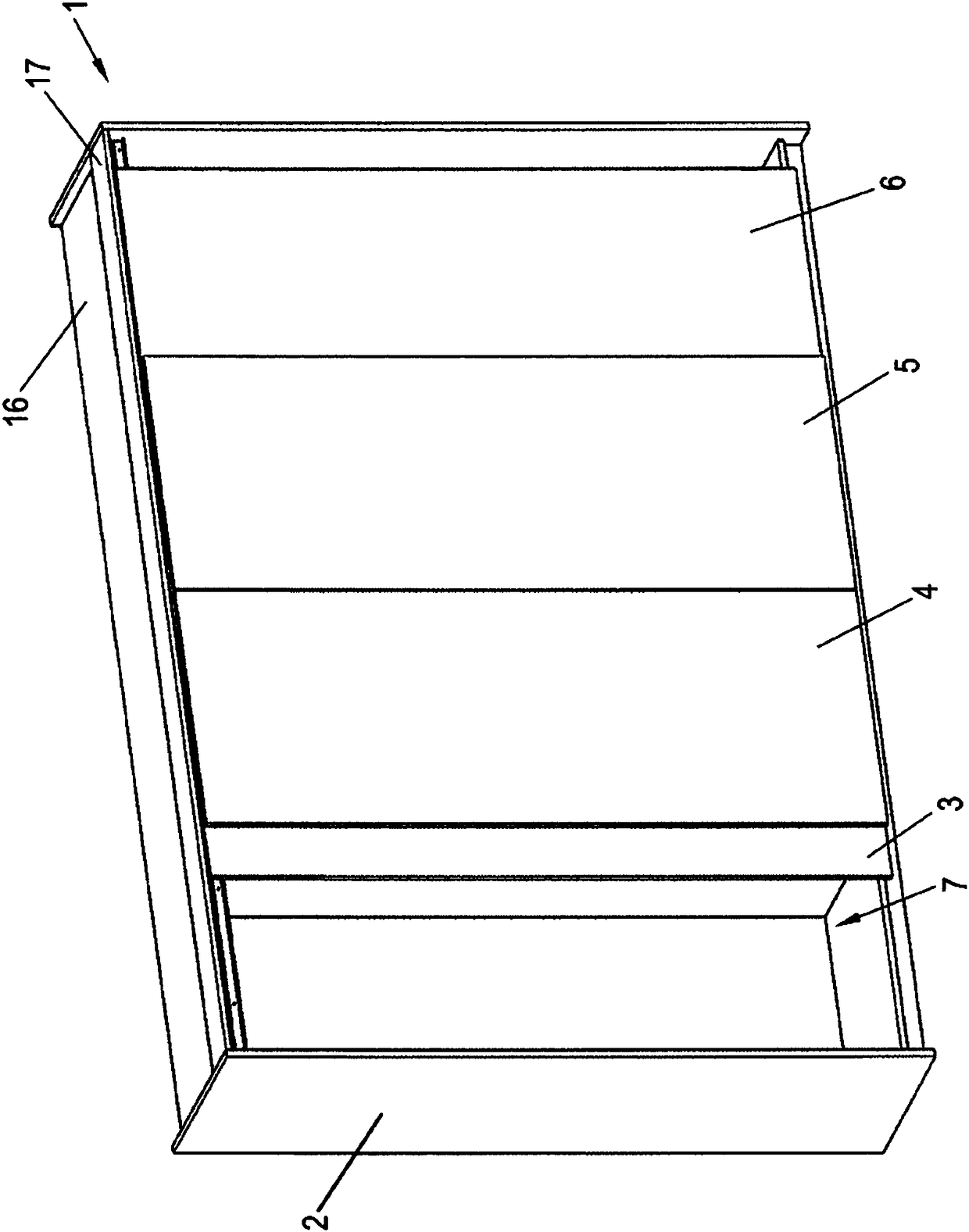
[0038] exist figure 2 In , the outer sliding doors 3 and 6 have been opened slightly, so that the interior space 7 of the furniture body 2 is partially accessible. The outer sliding doors 3 and 6 are movable independently and in the plane behind the middle sliding doors 4 and 5 .
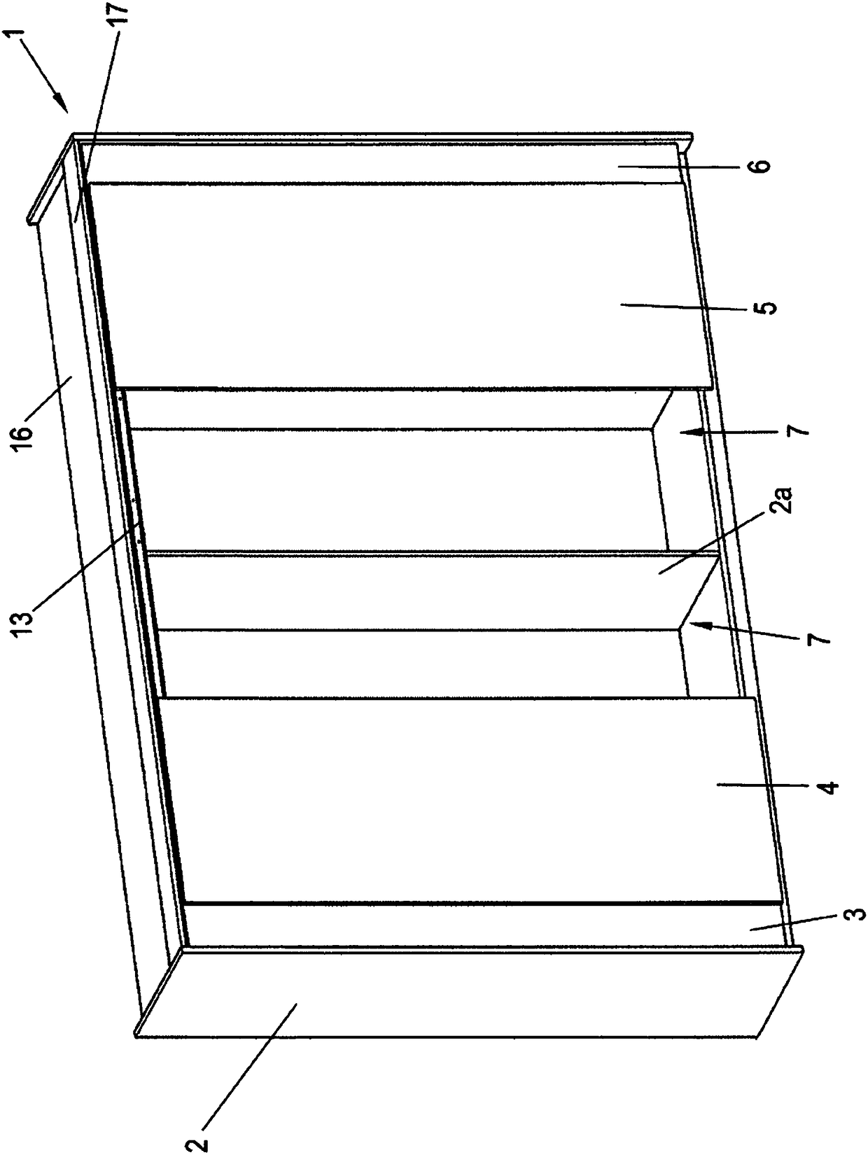
[0039] exist image 3 Among them, the middle sliding doors 4 and 5 have each been moved outward in opposite directions, so that the interior space 7 located at the rear and further divided by the main body center wall 2a can be entered for use. For a correspondingly more rigid design of the furniture body 2 and for a suitable inner configuration of the cabinet unit 1 , the body central wall 2 a can also be omitted. The s...
PUM
 Abstract
Description
Claims
Application Information
 - Generate Ideas
- Intellectual Property
- Life Sciences
- Materials
- Tech Scout
- Unparalleled Data Quality
- Higher Quality Content
- 60% Fewer Hallucinations
Browse by: Latest US Patents, China's latest patents, Technical Efficacy Thesaurus, Application Domain, Technology Topic, Popular Technical Reports.
© 2025 PatSnap. All rights reserved.Legal|Privacy policy|Modern Slavery Act Transparency Statement|Sitemap|About US| Contact US: help@patsnap.com