Connector

A technology of connectors and grounding terminals, which is applied in the direction of connection, two-part connection devices, and parts of connection devices, and can solve problems such as difficulty in obtaining impedance matching, increased number of connector parts, and complex internal structure of the connector.

Active Publication Date: 2018-07-31
HIROSE ELECTRIC GROUP
View PDF6 Cites 2 Cited by
  • Summary
  • Abstract
  • Description
  • Claims
  • Application Information

AI Technical Summary

Problems solved by technology

[0005] However, such ground terminals need to be distinguished from the signal terminals, and one terminal is arranged between a pair of signal terminals in a pair, or between a pair of signal terminals on one side and a pair of signal terminals on the other side. As mentioned above, there is a problem that the number of parts constituting the connector increases, and the internal structure of the connector becomes complicated.
In addition, the internal structure of the connector becomes complicated, so it may be difficult to achieve impedance matching

Method used


Image

  • Connector
  • Connector
  • Connector

Examples


Embodiment Construction

[0025] Hereinafter, embodiments of the present invention will be described with reference to the drawings. In addition, in all the drawings for explaining the embodiment, in principle, the same reference numerals are assigned to the same components, and repeated description thereof will be omitted. In addition, although each embodiment is demonstrated independently, it does not exclude the case where a connector is comprised by combining the components of each other.

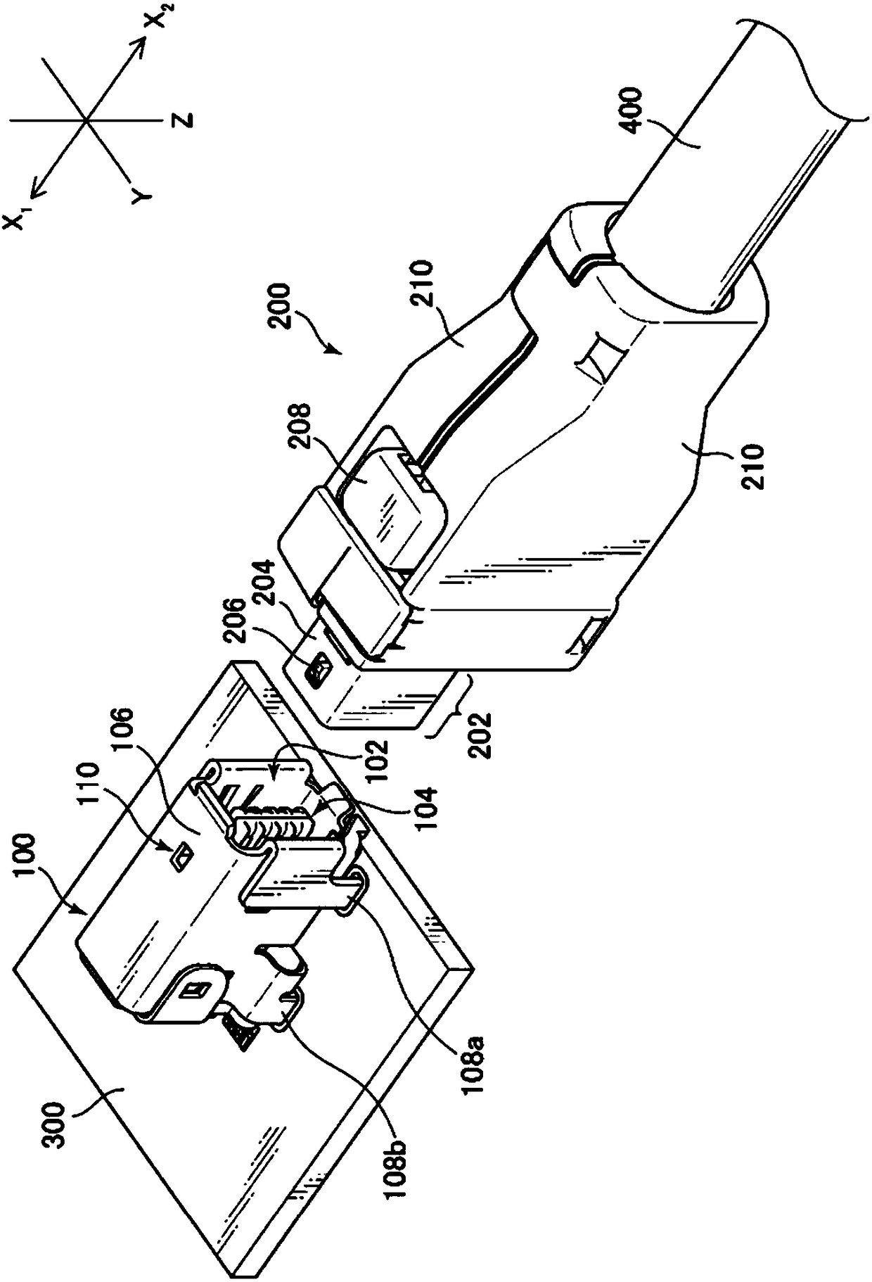
[0026] figure 1 It is a diagram showing the appearance of the connector on the board side and the connector on the cable side. The fitting direction of the connector is the X1-X2 direction (X-axis direction) in the figure. The front end side of the board-side connector 100 is the X2 direction side, and the front end side of the cable-side connector 200 is the X1 direction side. A plane perpendicular to the substrate 300 is an XZ plane, and a plane (parallel plane) to the substrate 300 is an XY plane. Let the...


PUM


Abstract

Conventional connectors had the problem that, because in addition to the signal terminals it was necessary to arrange one or more ground terminals between two signal terminal pairs, or between one pair of signal terminals and another pair of signal terminals, the number of components configuring the connector increased, making the internal structure of the connector more complicated. This substrate-side connector is provided with two terminal groups which are arranged so as to face one another along the fitting direction of the connector, an insulator which holds said terminal groups, and an external conductor shell which houses said insulator, wherein a shell mounting unit, for mounting the external conductor shell on the substrate, is passed between the two terminal groups and mounted between a group of terminal mounting units of the terminals included in one terminal group and a group of terminal mounting units of multiple terminals included in the other terminal group, and therebythe shell mounting unit of said external conductor shell can function as a ground terminal.

Description

technical field [0001] The present invention relates to a connector suitable for high-speed transmission of electrical signals. Specifically, it relates to a structure of a plurality of terminals arranged and configured to maintain impedance matching among a plurality of terminals included in a connector. Background technique [0002] Among connectors used for transmitting electrical signals and the like, there are generally connectors that include an insulator holding a plurality of conductive terminals and an outer conductor housing that accommodates the insulator. For example, the connector described in Japanese Patent No. 4439540 (Patent Document 1) is not only provided with a pair of two signal terminals, but also provides a ground terminal, and the ground terminal is arranged in a pair of two. between a pair of signal terminals, or between a pair of signal terminals on one side and a pair of signal terminals on the other side. [0003] Patent Document 1: Japanese Pat...

Claims


Application Information

Patent Timeline
Patent Type & Authority Applications(China)
IPC IPC(8): H01R13/6581H01R24/64
CPCH01R12/716H01R13/6473H01R13/6594H01R24/60H01R2107/00H01R13/6581H01R24/64
Inventor 境泽直志长沼健一
Owner HIROSE ELECTRIC GROUP
Why Eureka
Try Eureka