Sickbed

A technology of hospital bed and bed body, which is applied in the field of hospital beds, can solve the problems of reducing the work efficiency of medical staff and not being able to satisfy patients in real time, so as to avoid hindering actions, increase the effect of use, and improve work efficiency

Pending Publication Date: 2018-08-03
李学美
View PDF0 Cites 9 Cited by
  • Summary
  • Abstract
  • Description
  • Claims
  • Application Information

AI Technical Summary

Problems solved by technology

[0004] The purpose of the present invention is to provide a hospital bed to solve the problem that the bed block of the existing hospital bed needs to be manually adjusted, which cannot meet the needs of patients in real time and reduces the working efficiency of medical staff

Method used


Image

  • Sickbed
  • Sickbed
  • Sickbed

Examples


Embodiment 1

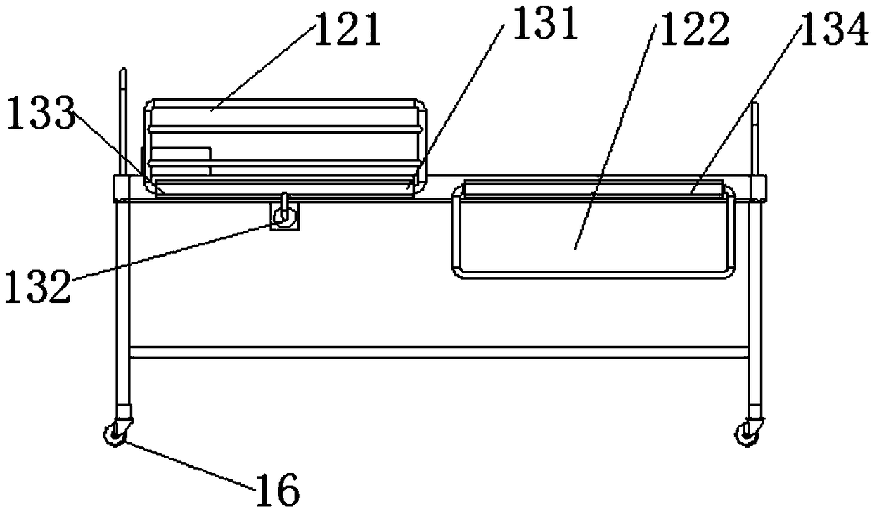
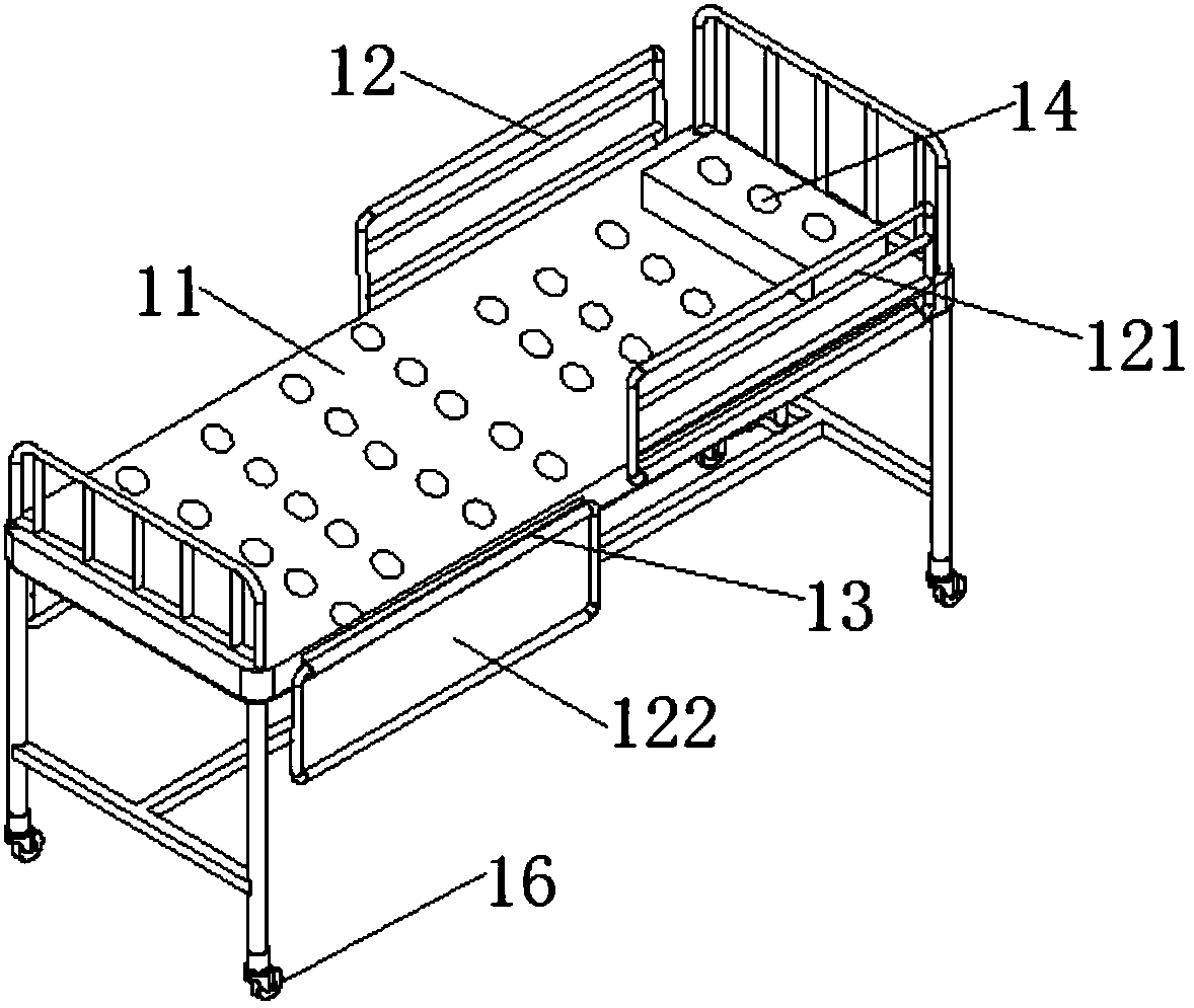
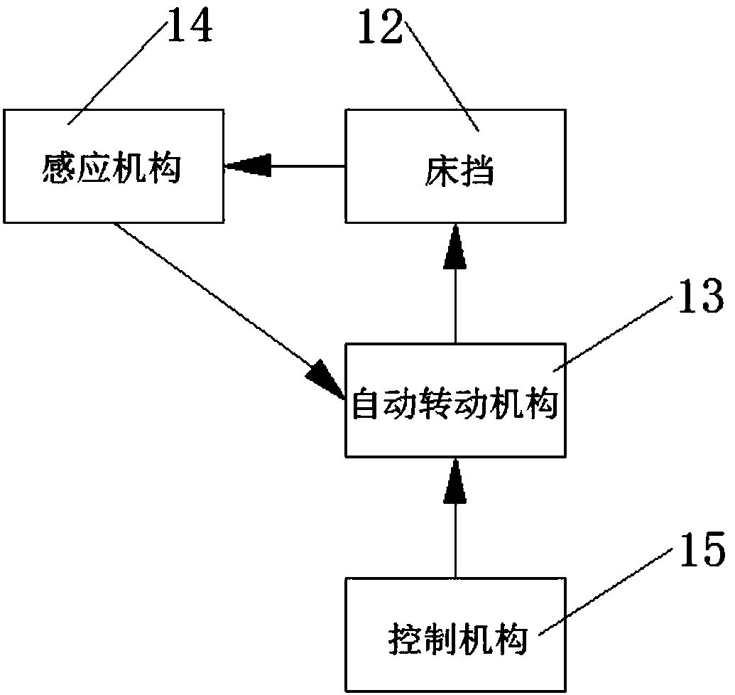
[0038] figure 1 The side view of the hospital bed provided for Embodiment 1 of the present invention; figure 2 Schematic diagram of the structure of the hospital bed provided by Embodiment 1 of the present invention; image 3 It is a block flow diagram of the hospital bed provided by Embodiment 1 of the present invention.

[0039] like Figure 1-3 As shown, the sick bed provided by the present invention includes a bed body 11, a bed stopper 12 and an automatic rotation mechanism 13; the bed stopper 12 is hinged to the bed body 11, and the automatic rotation mechanism 13 is located between the bed stopper 12 and the The bed body 11 is hinged to automatically regulate the angle between the bed block 12 and the bed body 11; the bed body 11 is provided with an induction mechanism 14, and one end of the induction mechanism 14 is connected to the bed body 11, and the other end is connected with the automatic rotation mechanism 13, so as to transmit the sensed bed body 11 signal ...

Embodiment 2

[0070] Figure 5 The side view of the hospital bed provided for Embodiment 2 of the present invention; Image 6 It is a schematic structural diagram of the hospital bed provided by Embodiment 2 of the present invention.

[0071] like Figure 5-6As shown, in this embodiment, the difference between the hospital bed and Embodiment 1 is that it includes a bed body 11, a bed stopper 12 and an automatic lifting mechanism 17; the bed stopper 12 is connected to the bed body 11, and the automatic lifting mechanism 17 is located at The joint between the bed block 12 and the bed body 11 is used to automatically regulate the position between the bed block 12 and the bed body 11; the bed body 11 is provided with an induction mechanism 14, and the induction mechanism 14 One end is connected with the bed body 11, and the other end is connected with the automatic lifting mechanism 17, so as to transmit the sensed signal of the bed body 11 to the automatic lifting mechanism 17, and control t...


PUM


Abstract

The invention provides a sickbed. The sickbed comprises a bed body, a bedrail and an automatic rotating mechanism. The bedrail is hinged to the bed body, the automatic rotating mechanism is located atthe hinged position of the bedrail and the bed body so as to automatically adjust and control the angle formed by the bedrail and the bed body. A sensing mechanism is arranged on the bed body, one end of the sensing mechanism is connected with the bed body, and the other end of the sensing mechanism is connected with the automatic rotating mechanism so as to transmit a sensed bed body signal to the automatic rotating mechanism and control the bedrail to rotate. The problem is solved that the bedrail of the sickbed needs to be adjusted and controlled annually, accordingly the demand of a patient cannot be met in real time and the working efficiency of medical workers is reduced. The sensing mechanism arranged on the bed body transmits the signal to the automatic rotating mechanism when sensing the body position change of the patient, and the automatic rotating mechanism controls the bedrail to rotate so that the bedrail can be located on the upper or lower side of the bed body, a protective effect can be played on the patient in real time, the bedrail can be also prevented from hindering movement of the patient, and the working efficiency of the medical workers can be improved.

Description

technical field [0001] The invention relates to the technical field of medical instruments, in particular to a sick bed. Background technique [0002] Hospital beds are also called medical beds and nursing beds. They are beds used by patients when recuperating. They are mainly used in major hospitals, township health centers, and community service centers. [0003] Most of the existing hospital beds simply include the bed body. For some patients with poor self-care ability, the bed body also needs to be provided with a bed stopper; the setting of the bed stopper can prevent the patient from falling from the bed when resting at night, causing harm to the body. , the bed block forms a relatively closed space for the patient, improving safety; the bed block needs to be pulled down when the patient needs to get out of bed, or when the nurse needs to check the patient, so as to avoid the bed block hindering the patient's movement and affecting the nurse's work Efficiency. After ...

Claims


Application Information

Patent Timeline
Patent Type & Authority Applications(China)
IPC IPC(8): A61G7/00A61G7/05
CPCA61G7/00A61G7/0509A61G7/052A61G2203/12A61G2203/34A61G2203/46
Inventor 李学美
Owner 李学美
Why Eureka
Try Eureka