Lubricating oil painting equipment for mechanical part

A technology of mechanical parts and lubricating oil, applied in the field of smearing equipment, which can solve the problems of low efficiency of manual smearing and uneven smearing

Inactive Publication Date: 2018-08-03
史志成
View PDF4 Cites 15 Cited by
  • Summary
  • Abstract
  • Description
  • Claims
  • Application Information

AI Technical Summary

Problems solved by technology

[0006] In order to overcome the disadvantages of low manual application efficiency and uneven application of lubricating oil on mechanical parts in the prior art, the technical problem to be solved by the present invention is to provide a mechanical part with high application efficiency and uniform application Lubricating oil application equipment

Method used


Image

  • Lubricating oil painting equipment for mechanical part
  • Lubricating oil painting equipment for mechanical part
  • Lubricating oil painting equipment for mechanical part

Examples


Embodiment 1

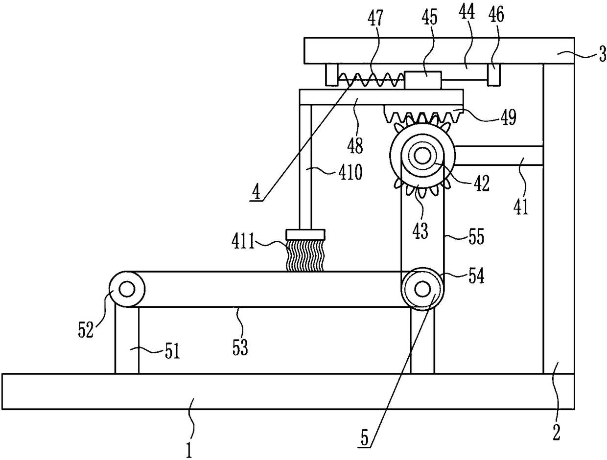
[0028] A lubricating oil application equipment for mechanical parts, such as Figure 1-3 As shown, it includes a base plate 1, a support plate 2, a top plate 3, a coating device 4 and a transmission device 5, the top right side of the base plate 1 is connected with a support plate 2, the top of the support plate 2 is connected with a top plate 3, and the bottom of the top plate 3 is provided There is a smearing device 4, and a conveying device 5 is arranged in the middle of the top of the bottom plate 1, and the smearing device 4 cooperates with the conveying device 5.

Embodiment 2

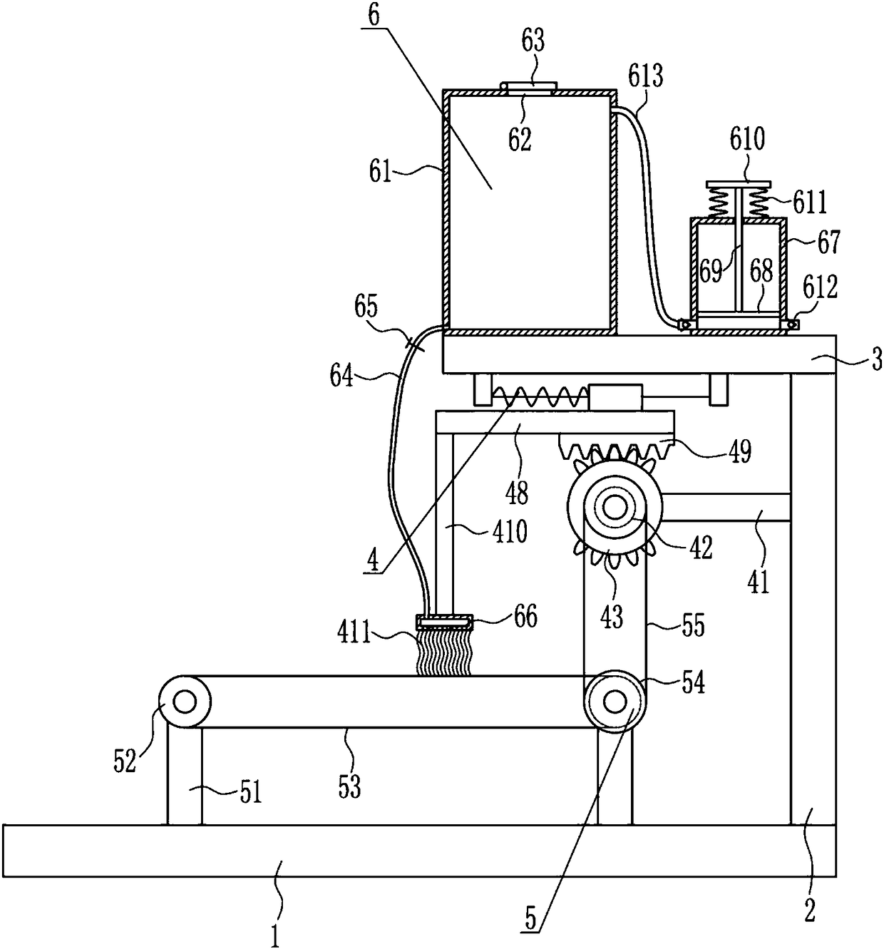
[0030] A lubricating oil application equipment for mechanical parts, such as Figure 1-3As shown, it includes a base plate 1, a support plate 2, a top plate 3, a coating device 4 and a transmission device 5, the top right side of the base plate 1 is connected with a support plate 2, the top of the support plate 2 is connected with a top plate 3, and the bottom of the top plate 3 is provided There is a smearing device 4, and a conveying device 5 is arranged in the middle of the top of the bottom plate 1, and the smearing device 4 cooperates with the conveying device 5.

[0031] The smearing device 4 includes a mounting rod 41, a motor 42, a missing tooth gear 43, a slide rail 44, a slide block 45, a block 46, a first spring 47, a movable plate 48, a rack 49, a connecting rod 410 and a first brush 411, the upper left side of the support plate 2 is connected with a mounting rod 41, the left end of the mounting rod 41 is equipped with a motor 42, the output shaft of the motor 42 i...

Embodiment 3

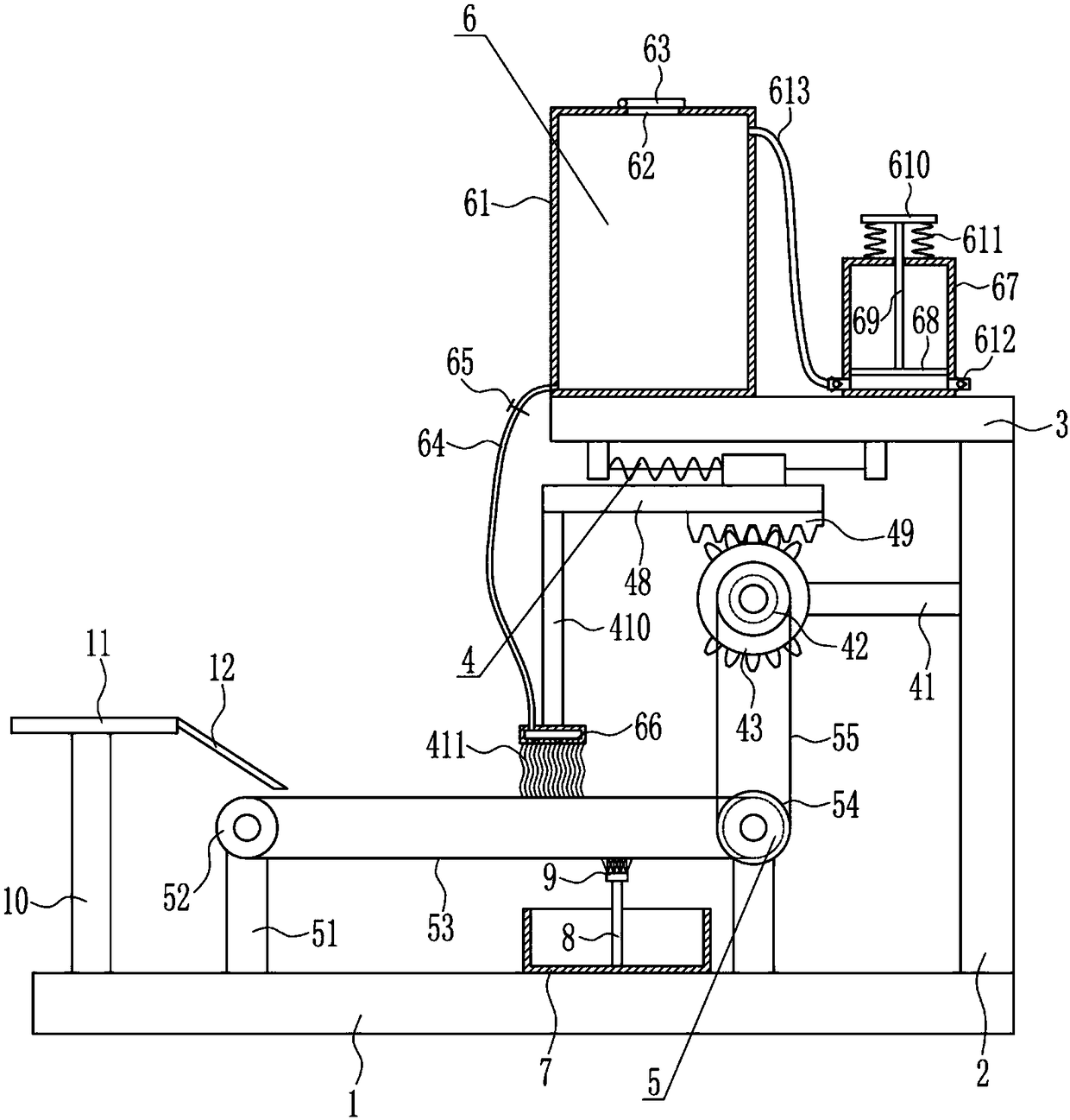
[0033] A lubricating oil application equipment for mechanical parts, such as Figure 1-3 As shown, it includes a base plate 1, a support plate 2, a top plate 3, a coating device 4 and a transmission device 5, the top right side of the base plate 1 is connected with a support plate 2, the top of the support plate 2 is connected with a top plate 3, and the bottom of the top plate 3 is provided There is a smearing device 4, and a conveying device 5 is arranged in the middle of the top of the bottom plate 1, and the smearing device 4 cooperates with the conveying device 5.

[0034] The smearing device 4 includes a mounting rod 41, a motor 42, a missing tooth gear 43, a slide rail 44, a slide block 45, a block 46, a first spring 47, a movable plate 48, a rack 49, a connecting rod 410 and a first brush 411, the upper left side of the support plate 2 is connected with a mounting rod 41, the left end of the mounting rod 41 is equipped with a motor 42, the output shaft of the motor 42 ...


PUM


Abstract

The invention relates to painting equipment, in particular to lubricating oil painting equipment for a mechanical part. The lubricating oil painting equipment for the mechanical part has high paintingefficiency and uniform smearing. The lubricating oil painting equipment comprises a bottom plate and the like. A supporting plate is connected with the right side of the top of the bottom plate, a top plate is connected with the top of the supporting plate, a painting device is arranged at the bottom of the top plate, a conveying device is arranged in the middle of the top of the bottom plate, and the painting device is matched with the conveying device. The mechanical part is driven to move to the right through the conveying device, the painting device smears lubricating oil on the mechanical part, and an oil conveying device drives the lubricating oil to uniformly flow onto a first brush, and thus painting is more uniform and the effects of high painting efficiency and uniform paintingare achieved.

Description

technical field [0001] The invention relates to a smearing device, in particular to a lubricating oil smearing device for mechanical parts. Background technique [0002] Mechanical parts, also known as mechanical components, are the basic components of machinery, and they are inseparable individual parts that make up machinery and machines. [0003] Lubricating oil is a liquid or semi-solid lubricant used in various types of automobiles and mechanical equipment to reduce friction and protect machinery and processed parts. It mainly plays the roles of lubrication, auxiliary cooling, rust prevention, cleaning, sealing and buffering. [0004] When mechanical parts are in use, lubricating oil needs to be applied on their surfaces so that the mechanical parts can reduce friction and prevent rust during use. Therefore, it is urgent to develop a lubricating oil application equipment for mechanical parts with high application efficiency and uniform application. Contents of the in...

Claims


Application Information

Patent Timeline
Patent Type & Authority Applications(China)
IPC IPC(8): B05C1/06B05C11/10B05C13/02
CPCB05C1/06B05C11/10B05C11/1039B05C13/02
Inventor 史志成李雪君黄莹莹
Owner 史志成
Why Eureka
Try Eureka