Glue dispensing equipment for integrated circuit packing

An integrated circuit and glue dispensing technology, which is applied to the surface coating liquid device, coating, etc., can solve the problems of high cost, time-consuming and laborious, and low efficiency of manual dispensing

Inactive Publication Date: 2018-01-09
怀化华晨电子科技有限公司
View PDF10 Cites 12 Cited by
  • Summary
  • Abstract
  • Description
  • Claims
  • Application Information

AI Technical Summary

Problems solved by technology

[0007] In order to overcome the shortcomings of low manual dispensing efficiency, time-consuming and laborious, and high cost of existing automatic dispensing equipment, the technical problem to be solved by the present invention is to provide an integrated Dispensing equipment for circuit packaging

Method used


Image

  • Glue dispensing equipment for integrated circuit packing
  • Glue dispensing equipment for integrated circuit packing
  • Glue dispensing equipment for integrated circuit packing

Examples


Embodiment 1

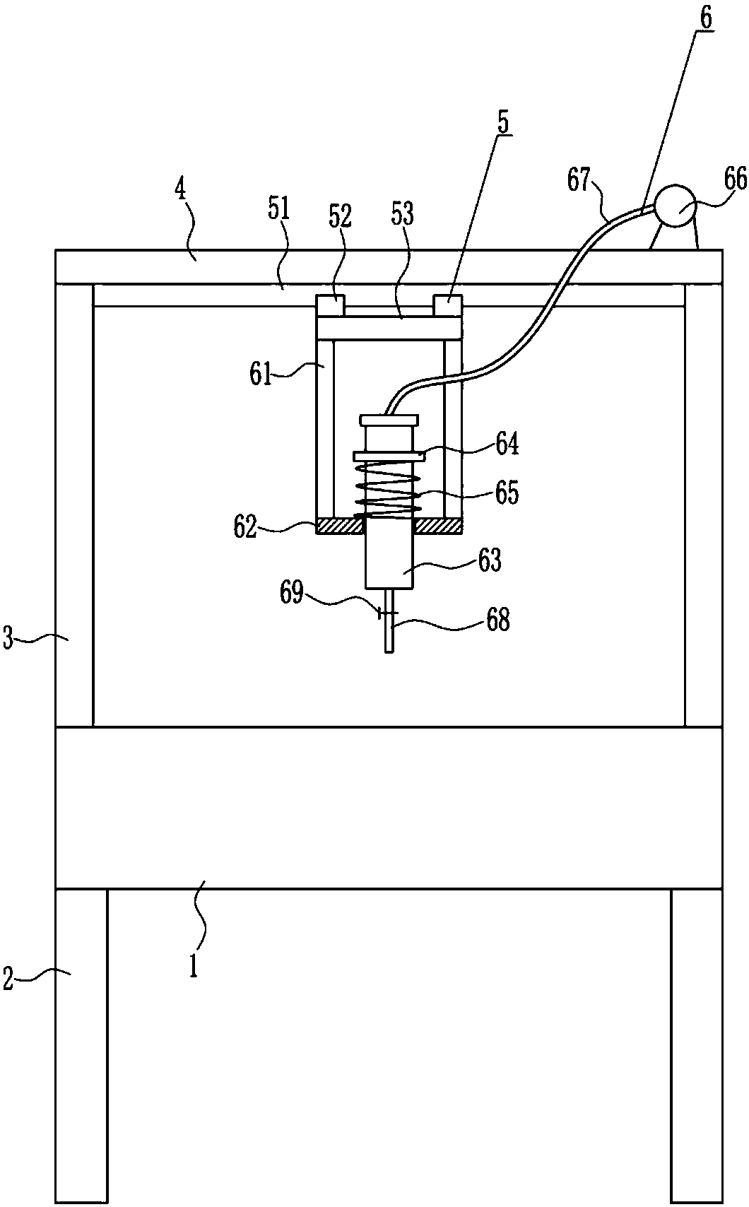
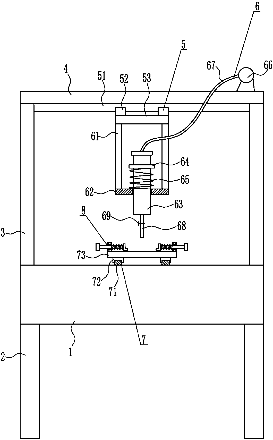
[0040] A dispensing equipment for integrated circuit packaging, such as Figure 1-8 As shown, it includes a box body 1, legs 2, bracket 3, top plate 4, left and right moving device 5 and glue dispensing device 6, and the four corners of the bottom of the box body 1 are equipped with legs 2 by means of bolt connection, and the box body 1 The left and right ends of the top are connected with a bracket 3, the top of the bracket 3 is connected with a top plate 4 through bolt connection, the bottom of the top plate 4 is provided with a left and right moving device 5, and the moving parts of the left and right moving device 5 are provided with a dispensing device 6 .

Embodiment 2

[0042] A dispensing equipment for integrated circuit packaging, such as Figure 1-8 As shown, it includes a box body 1, legs 2, bracket 3, top plate 4, left and right moving device 5 and glue dispensing device 6, and the four corners of the bottom of the box body 1 are equipped with legs 2 by means of bolt connection, and the box body 1 The left and right ends of the top are connected with a bracket 3, the top of the bracket 3 is connected with a top plate 4 through bolt connection, the bottom of the top plate 4 is provided with a left and right moving device 5, and the moving parts of the left and right moving device 5 are provided with a dispensing device 6 .

[0043] The left and right moving device 5 includes a first slide rail 51, a first slide block 52 and a movable plate 53. The bottom of the top plate 4 is connected with the first slide rail 51 by means of a bolt connection, and the first slide rail 51 is horizontally arranged on the left and right sides. A first slid...

Embodiment 3

[0045] A dispensing equipment for integrated circuit packaging, such as Figure 1-8 As shown, it includes a box body 1, legs 2, bracket 3, top plate 4, left and right moving device 5 and glue dispensing device 6, and the four corners of the bottom of the box body 1 are equipped with legs 2 by means of bolt connection, and the box body 1 The left and right ends of the top are connected with a bracket 3, the top of the bracket 3 is connected with a top plate 4 through bolt connection, the bottom of the top plate 4 is provided with a left and right moving device 5, and the moving parts of the left and right moving device 5 are provided with a dispensing device 6 .

[0046] The left and right moving device 5 includes a first slide rail 51, a first slide block 52 and a movable plate 53. The bottom of the top plate 4 is connected with the first slide rail 51 by means of a bolt connection, and the first slide rail 51 is horizontally arranged on the left and right sides. A first slid...


PUM


Abstract

The invention relates to glue dispensing equipment, in particular to glue dispensing equipment for integrated circuit packing. The technical problem to be solved by the invention is to provide the glue dispensing equipment for integrated circuit packing with high glue dispensing efficiency, time and labor saving and low manufacturing cost. In order to solve the technical problem, the invention provides the glue dispensing equipment for integrated circuit packing. The glue dispensing equipment for integrated circuit packing comprises a box and the like; support legs are mounted at four cornersof the bottom of the box through a bolt connecting mode; brackets are connected to the left and right ends of the top of the box; the tops of the brackets are connected with a top plate through a boltconnecting mode; a left-right moving device is arranged at the bottom of the top plate; and a moving part of the left-right moving device is provided with a glue dispensing device. A front-back moving device is driven to operate through a first driving device; a circuit board is fixed by a clamping device; and the left-right moving device is driven to operate by a second driving device, so that the glue dispensing device dispenses glue on the circuit board, and the effects of high glue dispensing efficiency, time and labor saving and low manufacturing cost are achieved.

Description

technical field [0001] The invention relates to a dispensing device, in particular to a dispensing device for integrated circuit packaging. Background technique [0002] An integrated circuit is a tiny electronic device or component. Using a certain process, the transistors, resistors, capacitors, inductors and other components required in a circuit are interconnected, and they are fabricated on a small or several small semiconductor wafers or dielectric substrates, and then packaged in a tube. , and become a microstructure with required circuit functions; all the components in it have been structurally integrated, making electronic components a big step towards miniaturization, low power consumption, intelligence and high reliability. [0003] Packaging is the process of assembling integrated circuits into chip final products. Simply put, it is to put the produced integrated circuit die on a substrate that acts as a load bearing, lead out the pins, and then fix and package...

Claims


Application Information

Patent Timeline
Patent Type & Authority Applications(China)
IPC IPC(8): B05C5/02B05C13/02
Inventor 杨月权刘苗方晓晨
Owner 怀化华晨电子科技有限公司
Why Eureka
Try Eureka